

98
5 Development of a Simulation-based Methodology …
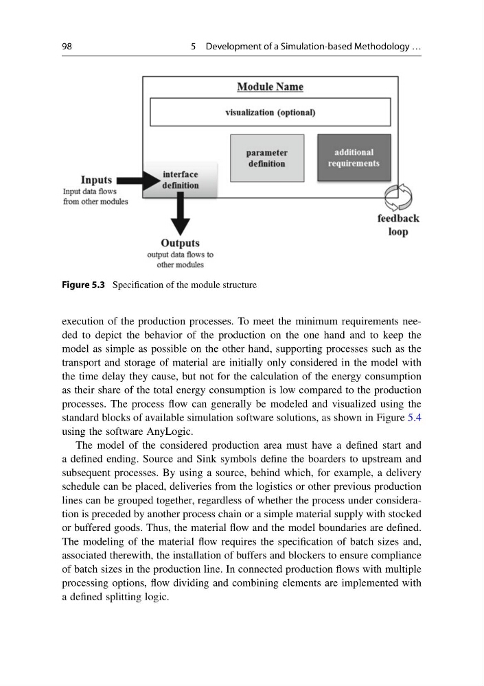
Figure 5.3 Specification of the module structure
execution of the production processes. To meet the minimum requirements needed to depict the behavior of the production on the one hand and to keep the
model as simple as possible on the other hand, supporting processes such as the
transport and storage of material are initially only considered in the model with
the time delay they cause, but not for the calculation of the energy consumption
as their share of the total energy consumption is low compared to the production
processes. The process flow can generally be modeled and visualized using the
standard blocks of available simulation software solutions, as shown in Figure 5.4
using the software AnyLogic.
The model of the considered production area must have a defined start and
a defined ending. Source and Sink symbols define the boarders to upstream and
subsequent processes. By using a source, behind which, for example, a delivery
schedule can be placed, deliveries from the logistics or other previous production
lines can be grouped together, regardless of whether the process under consideration is preceded by another process chain or a simple material supply with stocked
or buffered goods. Thus, the material flow and the model boundaries are defined.
The modeling of the material flow requires the specification of batch sizes and,
associated therewith, the installation of buffers and blockers to ensure compliance
of batch sizes in the production line. In connected production flows with multiple
processing options, flow dividing and combining elements are implemented with
a defined splitting logic.
5 Development of a Simulation-based Methodology …
Figure 5.3 Specification of the module structure
execution of the production processes. To meet the minimum requirements needed to depict the behavior of the production on the one hand and to keep the
model as simple as possible on the other hand, supporting processes such as the
transport and storage of material are initially only considered in the model with
the time delay they cause, but not for the calculation of the energy consumption
as their share of the total energy consumption is low compared to the production
processes. The process flow can generally be modeled and visualized using the
standard blocks of available simulation software solutions, as shown in Figure 5.4
using the software AnyLogic.
The model of the considered production area must have a defined start and
a defined ending. Source and Sink symbols define the boarders to upstream and
subsequent processes. By using a source, behind which, for example, a delivery
schedule can be placed, deliveries from the logistics or other previous production
lines can be grouped together, regardless of whether the process under consideration is preceded by another process chain or a simple material supply with stocked
or buffered goods. Thus, the material flow and the model boundaries are defined.
The modeling of the material flow requires the specification of batch sizes and,
associated therewith, the installation of buffers and blockers to ensure compliance
of batch sizes in the production line. In connected production flows with multiple
processing options, flow dividing and combining elements are implemented with
a defined splitting logic.