

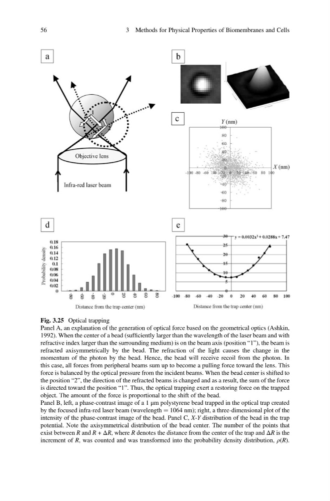
Fig. 3.25 Optical trapping
Panel A, an explanation of the generation of optical force based on the geometrical optics (Ashkin,
1992). When the center of a bead (sufficiently larger than the wavelength of the laser beam and with
refractive index larger than the surrounding medium) is on the beam axis (position “1”), the beam is
refracted axisymmetrically by the bead. The refraction of the light causes the change in the
momentum of the photon by the bead. Hence, the bead will receive recoil from the photon. In
this case, all forces from peripheral beams sum up to become a pulling force toward the lens. This
force is balanced by the optical pressure from the incident beams. When the bead center is shifted to
the position “2”, the direction of the refracted beams is changed and as a result, the sum of the force
is directed toward the position “1”. Thus, the optical trapping exert a restoring force on the trapped
object. The amount of the force is proportional to the shift of the bead.
Panel B, left, a phase-contrast image of a 1 μm polystyrene bead trapped in the optical trap created
by the focused infra-red laser beam (wavelength ¼ 1064 nm); right, a three-dimensional plot of the
intensity of the phase-contrast image of the bead. Panel C, X-Y distribution of the bead in the trap
potential. Note the axisymmetrical distribution of the bead center. The number of the points that
exist between R and R + ΔR, where R denotes the distance from the center of the trap and ΔR is the
increment of R, was counted and was transformed into the probability density distribution, ρ(R).
56
3 Methods for Physical Properties of Biomembranes and Cells
Panel A, an explanation of the generation of optical force based on the geometrical optics (Ashkin,
1992). When the center of a bead (sufficiently larger than the wavelength of the laser beam and with
refractive index larger than the surrounding medium) is on the beam axis (position “1”), the beam is
refracted axisymmetrically by the bead. The refraction of the light causes the change in the
momentum of the photon by the bead. Hence, the bead will receive recoil from the photon. In
this case, all forces from peripheral beams sum up to become a pulling force toward the lens. This
force is balanced by the optical pressure from the incident beams. When the bead center is shifted to
the position “2”, the direction of the refracted beams is changed and as a result, the sum of the force
is directed toward the position “1”. Thus, the optical trapping exert a restoring force on the trapped
object. The amount of the force is proportional to the shift of the bead.
Panel B, left, a phase-contrast image of a 1 μm polystyrene bead trapped in the optical trap created
by the focused infra-red laser beam (wavelength ¼ 1064 nm); right, a three-dimensional plot of the
intensity of the phase-contrast image of the bead. Panel C, X-Y distribution of the bead in the trap
potential. Note the axisymmetrical distribution of the bead center. The number of the points that
exist between R and R + ΔR, where R denotes the distance from the center of the trap and ΔR is the
increment of R, was counted and was transformed into the probability density distribution, ρ(R).
56
3 Methods for Physical Properties of Biomembranes and Cells