

42
3 Materials and Methods
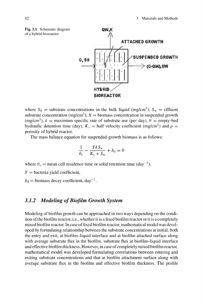
Fig. 3.1 Schematic diagram
of a hybrid bioreactor
where S 0 = substrate concentrations in the bulk liquid (mg/cm
3 ), S w = effluent
substrate concentration (mg/cm
3 ), X = biomass concentration in suspended growth
(mg/cm
3 ), k = maximum specific rate of substrate use (per day), θ = empty-bed
hydraulic detention time (day), K s = half velocity coefficient (mg/cm
3 ) and p =
porosity of hybrid reactor.
The mass balance equation for suspended-growth biomass is as follows:
1
θ c
−
Y kS w
K s + S w
+ b d = 0
where θ c = mean cell residence time or solid retention time (day
−1 ).
Y = bacteria yield coefficient,
b d = biomass decay coefficient, day
−1 .
3.1.2 Modeling of Biofilm Growth System
Modeling of biofilm growth can be approached in two ways depending on the condition of the biofilm reactor, i.e., whether it is a fixed biofilm reactor or it is a completely
mixed biofilm reactor. In case of fixed biofilm reactor, mathematical model was developed by formulating relationship between the substrate concentrations at initial, both
the entry and exit, at biofilm–liquid interface and at biofilm attached surface along
with average substrate flux in the biofilm, substrate flux at biofilm–liquid interface
and effective biofilm thickness. However, in case of completely mixed biofilm reactor,
mathematical model was developed formulating correlations between entering and
exiting substrate concentrations and that at biofilm attachment surface along with
average substrate flux in the biofilm and effective biofilm thickness. The profile
3 Materials and Methods
Fig. 3.1 Schematic diagram
of a hybrid bioreactor
where S 0 = substrate concentrations in the bulk liquid (mg/cm
3 ), S w = effluent
substrate concentration (mg/cm
3 ), X = biomass concentration in suspended growth
(mg/cm
3 ), k = maximum specific rate of substrate use (per day), θ = empty-bed
hydraulic detention time (day), K s = half velocity coefficient (mg/cm
3 ) and p =
porosity of hybrid reactor.
The mass balance equation for suspended-growth biomass is as follows:
1
θ c
−
Y kS w
K s + S w
+ b d = 0
where θ c = mean cell residence time or solid retention time (day
−1 ).
Y = bacteria yield coefficient,
b d = biomass decay coefficient, day
−1 .
3.1.2 Modeling of Biofilm Growth System
Modeling of biofilm growth can be approached in two ways depending on the condition of the biofilm reactor, i.e., whether it is a fixed biofilm reactor or it is a completely
mixed biofilm reactor. In case of fixed biofilm reactor, mathematical model was developed by formulating relationship between the substrate concentrations at initial, both
the entry and exit, at biofilm–liquid interface and at biofilm attached surface along
with average substrate flux in the biofilm, substrate flux at biofilm–liquid interface
and effective biofilm thickness. However, in case of completely mixed biofilm reactor,
mathematical model was developed formulating correlations between entering and
exiting substrate concentrations and that at biofilm attachment surface along with
average substrate flux in the biofilm and effective biofilm thickness. The profile