

Optimization of TiO 2 –KMnO 4 Composites with Natural Dyes for …
399
FTO glass by the doctor blade method with an active area of 1 × 0.5 cm
2 . Then the
FTO glasses were sintered at 450 °C for 1.5 h. This sintered FTO glasses coated with
KMnO 4 –TiO 2 films were immersed in the synthesized dye for 1 h. After heating
around 80 °C, these films were gently washed in ethanol to remove any unadsorbed
dye.
2.4 Preparation of the Graphite Counter Electrode
Graphite powder of 1.5 g is mixed with 0.1 g of ethyl cellulose and 10 g of terpineol
was added into it to make a graphite paste for layering on the conductive side of
the FTO. Graphite paste was deposited by the doctor blade method similarly like
the working electrode fabrication process. Then the counter electrode was placed on
hotplate keeping the conductive surface top at a temperature 90 °C for drying. When
the paste was dried, it was sintered at 450 °C for 1 h.
2.5 Assembly of the DSSC
The working electrode and the graphite counter electrode were assembled into a
sandwich-like structure. The electrolyte solution was added to the active area of the
working electrode. Once the material of the working electrode absorbs the electrolyte,
it was assembled with a counter electrode keeping the two conductive sides of the
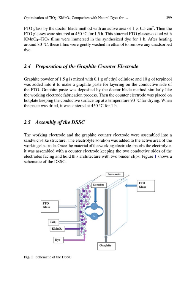
electrodes facing and hold this architecture with two binder clips. Figure 1 shows a
schematic of the DSSC.
Fig. 1 Schematic of the DSSC
399
FTO glass by the doctor blade method with an active area of 1 × 0.5 cm
2 . Then the
FTO glasses were sintered at 450 °C for 1.5 h. This sintered FTO glasses coated with
KMnO 4 –TiO 2 films were immersed in the synthesized dye for 1 h. After heating
around 80 °C, these films were gently washed in ethanol to remove any unadsorbed
dye.
2.4 Preparation of the Graphite Counter Electrode
Graphite powder of 1.5 g is mixed with 0.1 g of ethyl cellulose and 10 g of terpineol
was added into it to make a graphite paste for layering on the conductive side of
the FTO. Graphite paste was deposited by the doctor blade method similarly like
the working electrode fabrication process. Then the counter electrode was placed on
hotplate keeping the conductive surface top at a temperature 90 °C for drying. When
the paste was dried, it was sintered at 450 °C for 1 h.
2.5 Assembly of the DSSC
The working electrode and the graphite counter electrode were assembled into a
sandwich-like structure. The electrolyte solution was added to the active area of the
working electrode. Once the material of the working electrode absorbs the electrolyte,
it was assembled with a counter electrode keeping the two conductive sides of the
electrodes facing and hold this architecture with two binder clips. Figure 1 shows a
schematic of the DSSC.
Fig. 1 Schematic of the DSSC