

The Tribological Behavior of an In-Situ Processed Magnesium …
79
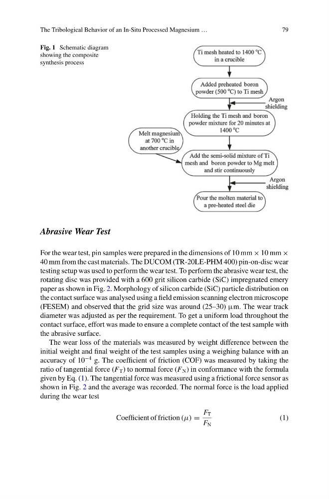
Fig. 1 Schematic diagram
showing the composite
synthesis process
Abrasive Wear Test
For the wear test, pin samples were prepared in the dimensions of 10 mm × 10 mm ×
40 mm from the cast materials. The DUCOM (TR-20LE-PHM 400) pin-on-disc wear
testing setup was used to perform the wear test. To perform the abrasive wear test, the
rotating disc was provided with a 600 grit silicon carbide (SiC) impregnated emery
paper as shown in Fig. 2. Morphology of silicon carbide (SiC) particle distribution on
the contact surface was analysed using a field emission scanning electron microscope
(FESEM) and observed that the grid size was around (25–30) µm. The wear track
diameter was adjusted as per the requirement. To get a uniform load throughout the
contact surface, effort was made to ensure a complete contact of the test sample with
the abrasive surface.
The wear loss of the materials was measured by weight difference between the
initial weight and final weight of the test samples using a weighing balance with an
accuracy of 10
−4 g. The coefficient of friction (COF) was measured by taking the
ratio of tangential force (F T ) to normal force (F N ) in conformance with the formula
given by Eq. (1). The tangential force was measured using a frictional force sensor as
shown in Fig. 2 and the average was recorded. The normal force is the load applied
during the wear test
Coefficient of friction (µ) =
F T
F N
(1)
79
Fig. 1 Schematic diagram
showing the composite
synthesis process
Abrasive Wear Test
For the wear test, pin samples were prepared in the dimensions of 10 mm × 10 mm ×
40 mm from the cast materials. The DUCOM (TR-20LE-PHM 400) pin-on-disc wear
testing setup was used to perform the wear test. To perform the abrasive wear test, the
rotating disc was provided with a 600 grit silicon carbide (SiC) impregnated emery
paper as shown in Fig. 2. Morphology of silicon carbide (SiC) particle distribution on
the contact surface was analysed using a field emission scanning electron microscope
(FESEM) and observed that the grid size was around (25–30) µm. The wear track
diameter was adjusted as per the requirement. To get a uniform load throughout the
contact surface, effort was made to ensure a complete contact of the test sample with
the abrasive surface.
The wear loss of the materials was measured by weight difference between the
initial weight and final weight of the test samples using a weighing balance with an
accuracy of 10
−4 g. The coefficient of friction (COF) was measured by taking the
ratio of tangential force (F T ) to normal force (F N ) in conformance with the formula
given by Eq. (1). The tangential force was measured using a frictional force sensor as
shown in Fig. 2 and the average was recorded. The normal force is the load applied
during the wear test
Coefficient of friction (µ) =
F T
F N
(1)