

Role of Microstructure on the Potential of MAX and MAB Phases …
31
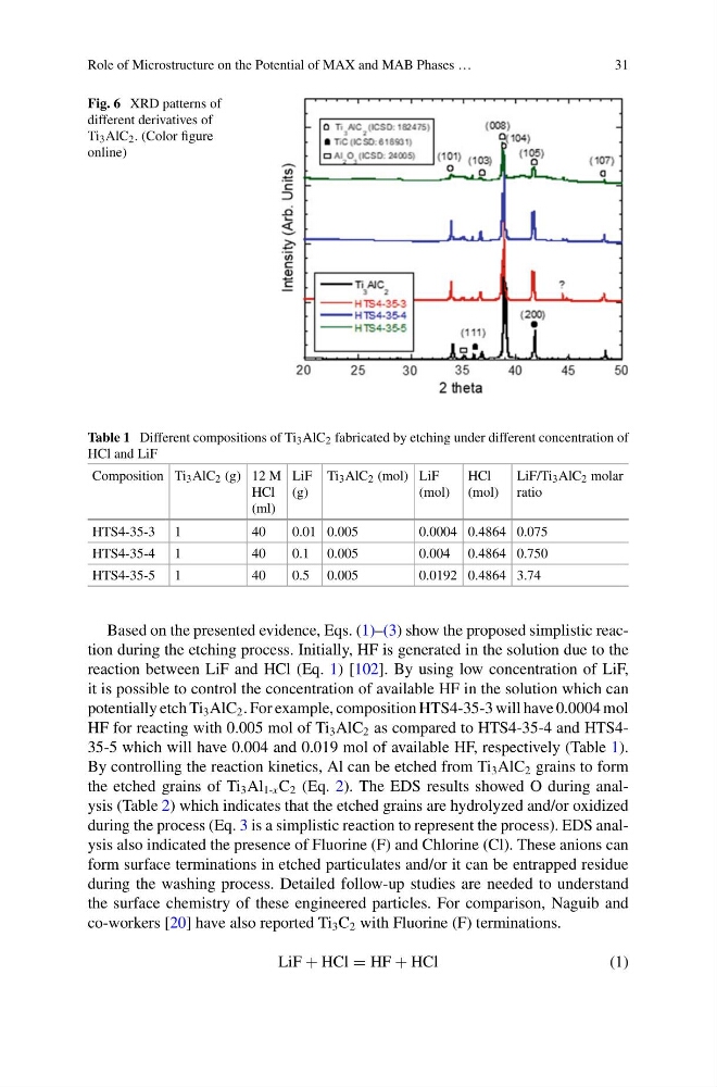
Fig. 6 XRD patterns of
different derivatives of
Ti 3 AlC 2 . (Color figure
online)
Table 1 Different compositions of Ti 3 AlC 2 fabricated by etching under different concentration of
HCl and LiF
Composition Ti 3 AlC 2 (g) 12 M
HCl
(ml)
LiF
(g)
Ti 3 AlC 2 (mol) LiF
(mol)
HCl
(mol)
LiF/Ti 3 AlC 2 molar
ratio
HTS4-35-3 1
40
0.01 0.005
0.0004 0.4864 0.075
HTS4-35-4 1
40
0.1 0.005
0.004 0.4864 0.750
HTS4-35-5 1
40
0.5 0.005
0.0192 0.4864 3.74
Based on the presented evidence, Eqs. (1)–(3) show the proposed simplistic reaction during the etching process. Initially, HF is generated in the solution due to the
reaction between LiF and HCl (Eq. 1) [102]. By using low concentration of LiF,
it is possible to control the concentration of available HF in the solution which can
potentially etch Ti 3 AlC 2 . For example, composition HTS4-35-3 will have 0.0004 mol
HF for reacting with 0.005 mol of Ti 3 AlC 2 as compared to HTS4-35-4 and HTS435-5 which will have 0.004 and 0.019 mol of available HF, respectively (Table 1).
By controlling the reaction kinetics, Al can be etched from Ti 3 AlC 2 grains to form
the etched grains of Ti 3 Al 1-x C 2 (Eq. 2). The EDS results showed O during analysis (Table 2) which indicates that the etched grains are hydrolyzed and/or oxidized
during the process (Eq. 3 is a simplistic reaction to represent the process). EDS analysis also indicated the presence of Fluorine (F) and Chlorine (Cl). These anions can
form surface terminations in etched particulates and/or it can be entrapped residue
during the washing process. Detailed follow-up studies are needed to understand
the surface chemistry of these engineered particles. For comparison, Naguib and
co-workers [20] have also reported Ti 3 C 2 with Fluorine (F) terminations.
LiF + HCl = HF + HCl
(1)
31
Fig. 6 XRD patterns of
different derivatives of
Ti 3 AlC 2 . (Color figure
online)
Table 1 Different compositions of Ti 3 AlC 2 fabricated by etching under different concentration of
HCl and LiF
Composition Ti 3 AlC 2 (g) 12 M
HCl
(ml)
LiF
(g)
Ti 3 AlC 2 (mol) LiF
(mol)
HCl
(mol)
LiF/Ti 3 AlC 2 molar
ratio
HTS4-35-3 1
40
0.01 0.005
0.0004 0.4864 0.075
HTS4-35-4 1
40
0.1 0.005
0.004 0.4864 0.750
HTS4-35-5 1
40
0.5 0.005
0.0192 0.4864 3.74
Based on the presented evidence, Eqs. (1)–(3) show the proposed simplistic reaction during the etching process. Initially, HF is generated in the solution due to the
reaction between LiF and HCl (Eq. 1) [102]. By using low concentration of LiF,
it is possible to control the concentration of available HF in the solution which can
potentially etch Ti 3 AlC 2 . For example, composition HTS4-35-3 will have 0.0004 mol
HF for reacting with 0.005 mol of Ti 3 AlC 2 as compared to HTS4-35-4 and HTS435-5 which will have 0.004 and 0.019 mol of available HF, respectively (Table 1).
By controlling the reaction kinetics, Al can be etched from Ti 3 AlC 2 grains to form
the etched grains of Ti 3 Al 1-x C 2 (Eq. 2). The EDS results showed O during analysis (Table 2) which indicates that the etched grains are hydrolyzed and/or oxidized
during the process (Eq. 3 is a simplistic reaction to represent the process). EDS analysis also indicated the presence of Fluorine (F) and Chlorine (Cl). These anions can
form surface terminations in etched particulates and/or it can be entrapped residue
during the washing process. Detailed follow-up studies are needed to understand
the surface chemistry of these engineered particles. For comparison, Naguib and
co-workers [20] have also reported Ti 3 C 2 with Fluorine (F) terminations.
LiF + HCl = HF + HCl
(1)