

204
A. Rabiei et al.
allowed to passively cool under high vacuum to room temperature. Detailed information regarding the manufacturing process of S-S CMF using powder metallurgy
technique can be found elsewhere [6, 9]. After processing, each S-S CMF panel
was cleaned and surface ground using a 35 × 150 cm Gallmeyer & Livingston Co.
“Grand Rapids” grinding machine to create a flat surface and uniform thickness of
1.59 cm. The samples were then used in a simulated pool fire testing set up that is
reported elsewhere [17, 18] and passed all requirements of the 49 CFR Part 179,
Appendix B, with a large margin.
In this study, the same samples were cleaned up to remove the oxide layer and
discoloration from the surface of the sample during the 100 min’ exposure of the
simulated pool fire testing. The cleanup of samples included a second set of surface
grinding using a 35 × 150 cm Gallmeyer & Livingston Co. “Grand Rapids” grinding
machine. Two of the three samples were used to conduct a scale down simulated torch
fire testing. Since the 15.9 mm S-S CMF panels have met the acceptance criteria for
the simulated pool fire test in 49 CFR 179 Appendix B by a large margin, the panels
were ground down to two thicknesses of 13.6 mm (equivalent to about six layers of
hollow spheres in the structure of S-S CMF panel) and 15.3 mm (equivalent to seven
layers of hollow spheres in S-S CMF panel) in order to pinpoint the exact thickness
required to meet the acceptance criteria for the simulated torch fire testing without
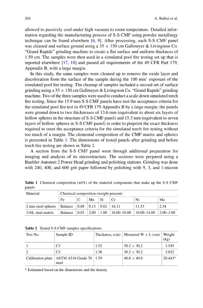
too much of a margin. The elemental composition of the CMF matrix and spheres
is presented in Table 1. The dimensions of tested panels after grinding and before
torch fire testing are shown in Table 2.
A section from the S-S CMF panel went through additional preparation for
imaging and analysis of its microstructure. The sections were prepared using a
Buehler Automet 2 Power Head grinding and polishing stations. Grinding was done
with 240, 400, and 600 grit paper followed by polishing with 9, 3, and 1-micron
Table 1 Chemical composition (wt%) of the material components that make up the S-S CMF
panels
Material
Chemical composition (weight percent)
Fe
C
Mn
Si
Cr
Ni
Mo
2 mm steel spheres Balance 0.68 0.13 0.82 16.11
11.53
2.34
316L steel matrix
Balance 0.03 2.00 1.00 16.00–18.00 10.00–14.00 2.00–3.00
Table 2 Tested S-S CMF samples specifications
Test No.
Sample ID
Thickness, (cm) Measured W × L (cm) Weight
(kg)
1
C3
1.52
30.2 × 30.2
3.545
2
C2
1.36
30.2 × 30.2
3.022
Calibration plate ASTM A516 Grade 70
steel
1.59
40.6 × 40.6
20.443*
* Estimated based on the dimensions and the density
A. Rabiei et al.
allowed to passively cool under high vacuum to room temperature. Detailed information regarding the manufacturing process of S-S CMF using powder metallurgy
technique can be found elsewhere [6, 9]. After processing, each S-S CMF panel
was cleaned and surface ground using a 35 × 150 cm Gallmeyer & Livingston Co.
“Grand Rapids” grinding machine to create a flat surface and uniform thickness of
1.59 cm. The samples were then used in a simulated pool fire testing set up that is
reported elsewhere [17, 18] and passed all requirements of the 49 CFR Part 179,
Appendix B, with a large margin.
In this study, the same samples were cleaned up to remove the oxide layer and
discoloration from the surface of the sample during the 100 min’ exposure of the
simulated pool fire testing. The cleanup of samples included a second set of surface
grinding using a 35 × 150 cm Gallmeyer & Livingston Co. “Grand Rapids” grinding
machine. Two of the three samples were used to conduct a scale down simulated torch
fire testing. Since the 15.9 mm S-S CMF panels have met the acceptance criteria for
the simulated pool fire test in 49 CFR 179 Appendix B by a large margin, the panels
were ground down to two thicknesses of 13.6 mm (equivalent to about six layers of
hollow spheres in the structure of S-S CMF panel) and 15.3 mm (equivalent to seven
layers of hollow spheres in S-S CMF panel) in order to pinpoint the exact thickness
required to meet the acceptance criteria for the simulated torch fire testing without
too much of a margin. The elemental composition of the CMF matrix and spheres
is presented in Table 1. The dimensions of tested panels after grinding and before
torch fire testing are shown in Table 2.
A section from the S-S CMF panel went through additional preparation for
imaging and analysis of its microstructure. The sections were prepared using a
Buehler Automet 2 Power Head grinding and polishing stations. Grinding was done
with 240, 400, and 600 grit paper followed by polishing with 9, 3, and 1-micron
Table 1 Chemical composition (wt%) of the material components that make up the S-S CMF
panels
Material
Chemical composition (weight percent)
Fe
C
Mn
Si
Cr
Ni
Mo
2 mm steel spheres Balance 0.68 0.13 0.82 16.11
11.53
2.34
316L steel matrix
Balance 0.03 2.00 1.00 16.00–18.00 10.00–14.00 2.00–3.00
Table 2 Tested S-S CMF samples specifications
Test No.
Sample ID
Thickness, (cm) Measured W × L (cm) Weight
(kg)
1
C3
1.52
30.2 × 30.2
3.545
2
C2
1.36
30.2 × 30.2
3.022
Calibration plate ASTM A516 Grade 70
steel
1.59
40.6 × 40.6
20.443*
* Estimated based on the dimensions and the density