

A Comparative Study on the Effect of Graphene and Multi-walled …
149
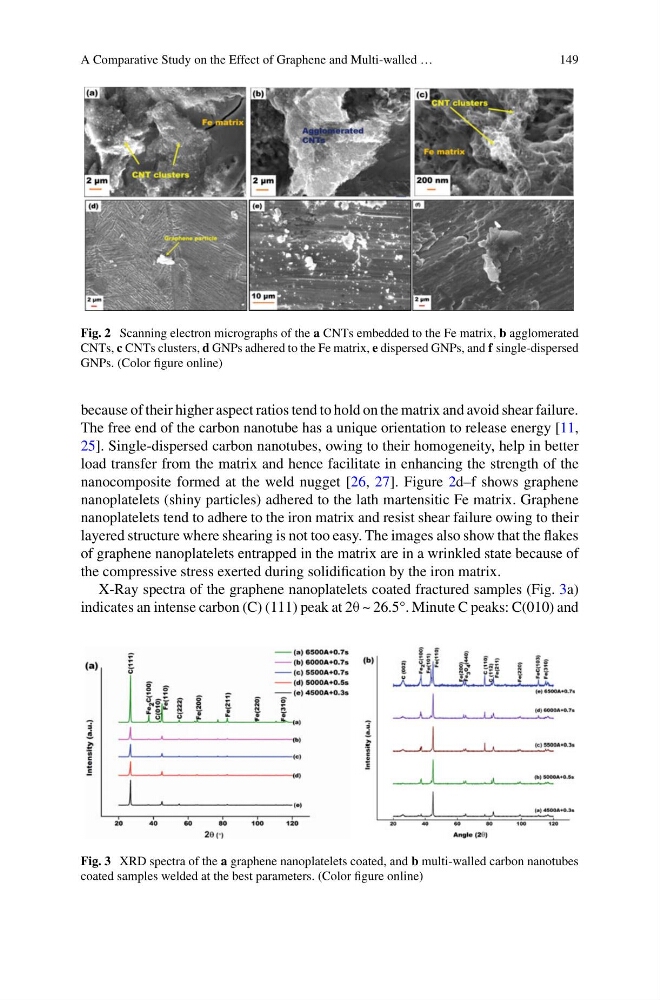
Fig. 2 Scanning electron micrographs of the a CNTs embedded to the Fe matrix, b agglomerated
CNTs, c CNTs clusters, d GNPs adhered to the Fe matrix, e dispersed GNPs, and f single-dispersed
GNPs. (Color figure online)
because of their higher aspect ratios tend to hold on the matrix and avoid shear failure.
The free end of the carbon nanotube has a unique orientation to release energy [11,
25]. Single-dispersed carbon nanotubes, owing to their homogeneity, help in better
load transfer from the matrix and hence facilitate in enhancing the strength of the
nanocomposite formed at the weld nugget [26, 27]. Figure 2d–f shows graphene
nanoplatelets (shiny particles) adhered to the lath martensitic Fe matrix. Graphene
nanoplatelets tend to adhere to the iron matrix and resist shear failure owing to their
layered structure where shearing is not too easy. The images also show that the flakes
of graphene nanoplatelets entrapped in the matrix are in a wrinkled state because of
the compressive stress exerted during solidification by the iron matrix.
X-Ray spectra of the graphene nanoplatelets coated fractured samples (Fig. 3a)
indicates an intense carbon (C) (111) peak at 2θ ~ 26.5°. Minute C peaks: C(010) and
Fig. 3 XRD spectra of the a graphene nanoplatelets coated, and b multi-walled carbon nanotubes
coated samples welded at the best parameters. (Color figure online)
149
Fig. 2 Scanning electron micrographs of the a CNTs embedded to the Fe matrix, b agglomerated
CNTs, c CNTs clusters, d GNPs adhered to the Fe matrix, e dispersed GNPs, and f single-dispersed
GNPs. (Color figure online)
because of their higher aspect ratios tend to hold on the matrix and avoid shear failure.
The free end of the carbon nanotube has a unique orientation to release energy [11,
25]. Single-dispersed carbon nanotubes, owing to their homogeneity, help in better
load transfer from the matrix and hence facilitate in enhancing the strength of the
nanocomposite formed at the weld nugget [26, 27]. Figure 2d–f shows graphene
nanoplatelets (shiny particles) adhered to the lath martensitic Fe matrix. Graphene
nanoplatelets tend to adhere to the iron matrix and resist shear failure owing to their
layered structure where shearing is not too easy. The images also show that the flakes
of graphene nanoplatelets entrapped in the matrix are in a wrinkled state because of
the compressive stress exerted during solidification by the iron matrix.
X-Ray spectra of the graphene nanoplatelets coated fractured samples (Fig. 3a)
indicates an intense carbon (C) (111) peak at 2θ ~ 26.5°. Minute C peaks: C(010) and
Fig. 3 XRD spectra of the a graphene nanoplatelets coated, and b multi-walled carbon nanotubes
coated samples welded at the best parameters. (Color figure online)