

34
2 RFID System Physical Anti-Collision Experimental Verification
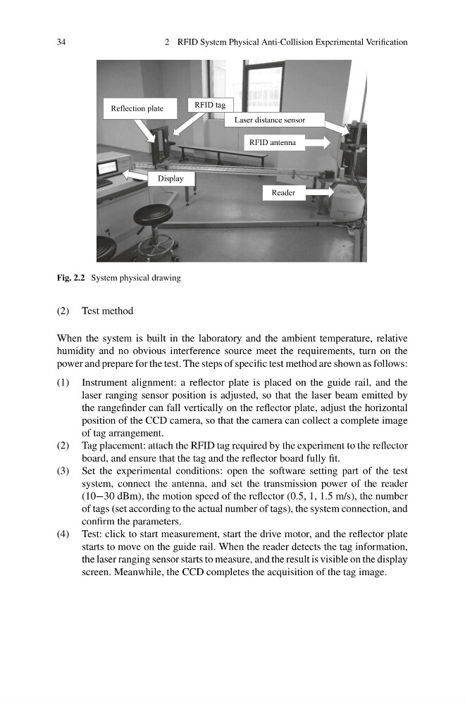
Fig. 2.2 System physical drawing
(2) Test method
When the system is built in the laboratory and the ambient temperature, relative
humidity and no obvious interference source meet the requirements, turn on the
power and prepare for the test. The steps of specific test method are shown as follows:
(1) Instrument alignment: a reflector plate is placed on the guide rail, and the
laser ranging sensor position is adjusted, so that the laser beam emitted by
the rangefinder can fall vertically on the reflector plate, adjust the horizontal
position of the CCD camera, so that the camera can collect a complete image
of tag arrangement.
(2) Tag placement: attach the RFID tag required by the experiment to the reflector
board, and ensure that the tag and the reflector board fully fit.
(3) Set the experimental conditions: open the software setting part of the test
system, connect the antenna, and set the transmission power of the reader
(10−30 dBm), the motion speed of the reflector (0.5, 1, 1.5 m/s), the number
of tags (set according to the actual number of tags), the system connection, and
confirm the parameters.
(4) Test: click to start measurement, start the drive motor, and the reflector plate
starts to move on the guide rail. When the reader detects the tag information,
the laser ranging sensor starts to measure, and the result is visible on the display
screen. Meanwhile, the CCD completes the acquisition of the tag image.
2 RFID System Physical Anti-Collision Experimental Verification
Fig. 2.2 System physical drawing
(2) Test method
When the system is built in the laboratory and the ambient temperature, relative
humidity and no obvious interference source meet the requirements, turn on the
power and prepare for the test. The steps of specific test method are shown as follows:
(1) Instrument alignment: a reflector plate is placed on the guide rail, and the
laser ranging sensor position is adjusted, so that the laser beam emitted by
the rangefinder can fall vertically on the reflector plate, adjust the horizontal
position of the CCD camera, so that the camera can collect a complete image
of tag arrangement.
(2) Tag placement: attach the RFID tag required by the experiment to the reflector
board, and ensure that the tag and the reflector board fully fit.
(3) Set the experimental conditions: open the software setting part of the test
system, connect the antenna, and set the transmission power of the reader
(10−30 dBm), the motion speed of the reflector (0.5, 1, 1.5 m/s), the number
of tags (set according to the actual number of tags), the system connection, and
confirm the parameters.
(4) Test: click to start measurement, start the drive motor, and the reflector plate
starts to move on the guide rail. When the reader detects the tag information,
the laser ranging sensor starts to measure, and the result is visible on the display
screen. Meanwhile, the CCD completes the acquisition of the tag image.