

144
4 Image Theory of RFID System Physical Anti-Collision
Z t = jZ 0 tan
ka
2
(4.42)
According to Eq. (4.42), when the impedance loop length a is increased, the
transmission line Z t portion is increased.
The coefficient α is determined by (4.43):
α =
ln b − ln 8.25w
ln b − ln 0.25w
(4.43)
According to Eq. (4.43), the matching impedance loop width b, the line width w,
and the antenna line width w
all affect the coefficient α, and thus, they can change the
antenna impedance. The influence of b on the coefficient is limited, and the change
of the w and w
will also have a certain effect on α, but the coefficient of w
is 8.25
and the coefficient of w is 0.25, so the impact of w on antenna impedance is greater
than that of w
. Therefore, the main parameters affecting impedance matching are
the length, width, and line width of the impedance matching loop.
Since the half-wave dipole operates in the ultra high frequency and the total length
of the tag antenna reaches 16 cm, this size of the antenna is very difficult to use in
most scenarios. In order to reduce the size of the label while working in the ultra high
frequency band, the dipole antenna is bent. According to Fig. 4.24, an antenna model
diagram is drawn. The dipole antenna is bent and the left and right radiators are bent
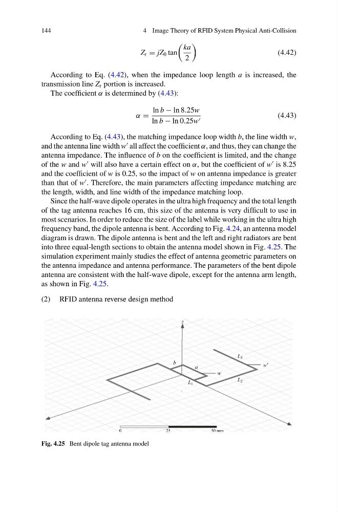
into three equal-length sections to obtain the antenna model shown in Fig. 4.25. The
simulation experiment mainly studies the effect of antenna geometric parameters on
the antenna impedance and antenna performance. The parameters of the bent dipole
antenna are consistent with the half-wave dipole, except for the antenna arm length,
as shown in Fig. 4.25.
(2) RFID antenna reverse design method
Fig. 4.25 Bent dipole tag antenna model
4 Image Theory of RFID System Physical Anti-Collision
Z t = jZ 0 tan
ka
2
(4.42)
According to Eq. (4.42), when the impedance loop length a is increased, the
transmission line Z t portion is increased.
The coefficient α is determined by (4.43):
α =
ln b − ln 8.25w
ln b − ln 0.25w
(4.43)
According to Eq. (4.43), the matching impedance loop width b, the line width w,
and the antenna line width w
all affect the coefficient α, and thus, they can change the
antenna impedance. The influence of b on the coefficient is limited, and the change
of the w and w
will also have a certain effect on α, but the coefficient of w
is 8.25
and the coefficient of w is 0.25, so the impact of w on antenna impedance is greater
than that of w
. Therefore, the main parameters affecting impedance matching are
the length, width, and line width of the impedance matching loop.
Since the half-wave dipole operates in the ultra high frequency and the total length
of the tag antenna reaches 16 cm, this size of the antenna is very difficult to use in
most scenarios. In order to reduce the size of the label while working in the ultra high
frequency band, the dipole antenna is bent. According to Fig. 4.24, an antenna model
diagram is drawn. The dipole antenna is bent and the left and right radiators are bent
into three equal-length sections to obtain the antenna model shown in Fig. 4.25. The
simulation experiment mainly studies the effect of antenna geometric parameters on
the antenna impedance and antenna performance. The parameters of the bent dipole
antenna are consistent with the half-wave dipole, except for the antenna arm length,
as shown in Fig. 4.25.
(2) RFID antenna reverse design method
Fig. 4.25 Bent dipole tag antenna model