

4.4 3D Space RFID Tag Location
137
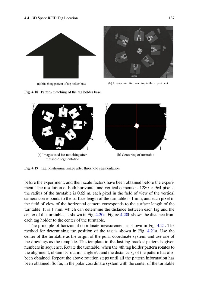
Fig. 4.18 Pattern matching of the tag holder base
(a) Images used for matching after
threshold segmentation
(b) Centering of turntable
Fig. 4.19 Tag positioning image after threshold segmentation
before the experiment, and their scale factors have been obtained before the experiment. The resolution of both horizontal and vertical cameras is 1280 × 964 pixels,
the radius of the turntable is 0.65 m, each pixel in the field of view of the vertical
camera corresponds to the surface length of the turntable is 1 mm, and each pixel in
the field of view of the horizontal camera corresponds to the surface length of the
turntable. It is 1 mm, which can determine the distance between each tag and the
center of the turntable, as shown in Fig. 4.20a. Figure 4.20b shows the distance from
each tag holder to the center of the turntable.
The principle of horizontal coordinate measurement is shown in Fig. 4.21. The
method for determining the position of the tag is shown in Fig. 4.21a. Use the
center of the turntable as the origin of the polar coordinate system, and use one of
the drawings as the template. The template to the last tag bracket pattern is given
numbers in sequence. Rotate the turntable, when the nth tag holder pattern rotates to
the alignment, obtain its rotation angle θ n , and the distance r n of the pattern has also
been obtained. Repeat the above rotation steps until all the pattern information has
been obtained. So far, in the polar coordinate system with the center of the turntable
137
Fig. 4.18 Pattern matching of the tag holder base
(a) Images used for matching after
threshold segmentation
(b) Centering of turntable
Fig. 4.19 Tag positioning image after threshold segmentation
before the experiment, and their scale factors have been obtained before the experiment. The resolution of both horizontal and vertical cameras is 1280 × 964 pixels,
the radius of the turntable is 0.65 m, each pixel in the field of view of the vertical
camera corresponds to the surface length of the turntable is 1 mm, and each pixel in
the field of view of the horizontal camera corresponds to the surface length of the
turntable. It is 1 mm, which can determine the distance between each tag and the
center of the turntable, as shown in Fig. 4.20a. Figure 4.20b shows the distance from
each tag holder to the center of the turntable.
The principle of horizontal coordinate measurement is shown in Fig. 4.21. The
method for determining the position of the tag is shown in Fig. 4.21a. Use the
center of the turntable as the origin of the polar coordinate system, and use one of
the drawings as the template. The template to the last tag bracket pattern is given
numbers in sequence. Rotate the turntable, when the nth tag holder pattern rotates to
the alignment, obtain its rotation angle θ n , and the distance r n of the pattern has also
been obtained. Repeat the above rotation steps until all the pattern information has
been obtained. So far, in the polar coordinate system with the center of the turntable