

3.3 Kinetic Analysis of Physical Anti-Collision …
103
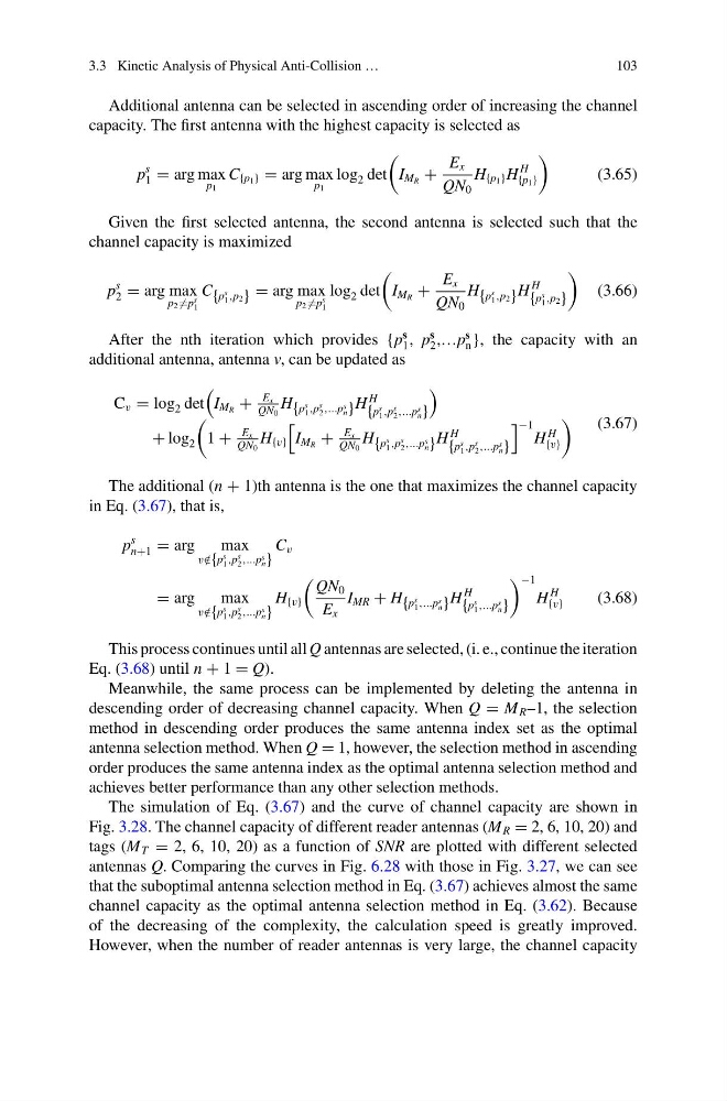
Additional antenna can be selected in ascending order of increasing the channel
capacity. The first antenna with the highest capacity is selected as
p
s
1 = arg max
p 1
C {p 1 } = arg max
p 1
log 2 det
I M R +
E x
QN 0
H {p 1 } H
H
{p 1 }
(3.65)
Given the first selected antenna, the second antenna is selected such that the
channel capacity is maximized
p
s
2 = arg max
p 2 =p
s
1
C {p
s
1 ,p 2 } = arg max
p 2 =p
s
1
log 2 det
I M R +
E x
QN 0
H {p
s
1 ,p 2 } H
H
{p
s
1 ,p 2 }
(3.66)
After the nth iteration which provides {p
s
1 , p
s
2 ,…p
s
n }, the capacity with an
additional antenna, antenna v, can be updated as
C v = log 2 det
I M R +
E x
QN 0
H {p
s
1 ,p
s
2 ,...p s
n } H
H
{p
s
1 ,p
s
2 ,...p s
n }
+ log 2
1 +
E x
QN 0
H {v}
I M R +
E x
QN 0
H {p
s
1 ,p
s
2 ,...p s
n } H
H
{p
s
1 ,p
s
2 ,...p s
n }
−1
H
H
{v}
(3.67)
The additional (n + 1)th antenna is the one that maximizes the channel capacity
in Eq. (3.67), that is,
p
s
n+1 = arg
max
v /
∈{p
s
1 ,p
s
2 ,...p s
n }
C v
= arg
max
v /
∈{p
s
1 ,p
s
2 ,...p s
n }
H {v}
QN 0
E x
I MR + H {p
s
1 ,...p s
n } H
H
{p
s
1 ,...p s
n }
−1
H
H
{v}
(3.68)
This process continues until all Q antennas are selected, (i. e., continue the iteration
Eq. (3.68) until n + 1 = Q).
Meanwhile, the same process can be implemented by deleting the antenna in
descending order of decreasing channel capacity. When Q = M R –1, the selection
method in descending order produces the same antenna index set as the optimal
antenna selection method. When Q = 1, however, the selection method in ascending
order produces the same antenna index as the optimal antenna selection method and
achieves better performance than any other selection methods.
The simulation of Eq. (3.67) and the curve of channel capacity are shown in
Fig. 3.28. The channel capacity of different reader antennas (M R = 2, 6, 10, 20) and
tags (M T = 2, 6, 10, 20) as a function of SNR are plotted with different selected
antennas Q. Comparing the curves in Fig. 6.28 with those in Fig. 3.27, we can see
that the suboptimal antenna selection method in Eq. (3.67) achieves almost the same
channel capacity as the optimal antenna selection method in Eq. (3.62). Because
of the decreasing of the complexity, the calculation speed is greatly improved.
However, when the number of reader antennas is very large, the channel capacity
103
Additional antenna can be selected in ascending order of increasing the channel
capacity. The first antenna with the highest capacity is selected as
p
s
1 = arg max
p 1
C {p 1 } = arg max
p 1
log 2 det
I M R +
E x
QN 0
H {p 1 } H
H
{p 1 }
(3.65)
Given the first selected antenna, the second antenna is selected such that the
channel capacity is maximized
p
s
2 = arg max
p 2 =p
s
1
C {p
s
1 ,p 2 } = arg max
p 2 =p
s
1
log 2 det
I M R +
E x
QN 0
H {p
s
1 ,p 2 } H
H
{p
s
1 ,p 2 }
(3.66)
After the nth iteration which provides {p
s
1 , p
s
2 ,…p
s
n }, the capacity with an
additional antenna, antenna v, can be updated as
C v = log 2 det
I M R +
E x
QN 0
H {p
s
1 ,p
s
2 ,...p s
n } H
H
{p
s
1 ,p
s
2 ,...p s
n }
+ log 2
1 +
E x
QN 0
H {v}
I M R +
E x
QN 0
H {p
s
1 ,p
s
2 ,...p s
n } H
H
{p
s
1 ,p
s
2 ,...p s
n }
−1
H
H
{v}
(3.67)
The additional (n + 1)th antenna is the one that maximizes the channel capacity
in Eq. (3.67), that is,
p
s
n+1 = arg
max
v /
∈{p
s
1 ,p
s
2 ,...p s
n }
C v
= arg
max
v /
∈{p
s
1 ,p
s
2 ,...p s
n }
H {v}
QN 0
E x
I MR + H {p
s
1 ,...p s
n } H
H
{p
s
1 ,...p s
n }
−1
H
H
{v}
(3.68)
This process continues until all Q antennas are selected, (i. e., continue the iteration
Eq. (3.68) until n + 1 = Q).
Meanwhile, the same process can be implemented by deleting the antenna in
descending order of decreasing channel capacity. When Q = M R –1, the selection
method in descending order produces the same antenna index set as the optimal
antenna selection method. When Q = 1, however, the selection method in ascending
order produces the same antenna index as the optimal antenna selection method and
achieves better performance than any other selection methods.
The simulation of Eq. (3.67) and the curve of channel capacity are shown in
Fig. 3.28. The channel capacity of different reader antennas (M R = 2, 6, 10, 20) and
tags (M T = 2, 6, 10, 20) as a function of SNR are plotted with different selected
antennas Q. Comparing the curves in Fig. 6.28 with those in Fig. 3.27, we can see
that the suboptimal antenna selection method in Eq. (3.67) achieves almost the same
channel capacity as the optimal antenna selection method in Eq. (3.62). Because
of the decreasing of the complexity, the calculation speed is greatly improved.
However, when the number of reader antennas is very large, the channel capacity