

512
14 Nanostructures Obtained with Plasma Discharge Processes
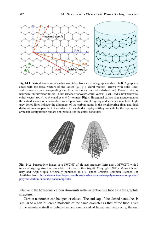
Fig. 14.1 Virtual formation of carbon nanotubes from slices of a graphene sheet. Left: A graphene
sheet with the basal vectors of the lattice (a 1 , a 2 ), chiral vectors (arrows with solid lines)
and nanowire axes corresponding the chiral vectors (arrows with dashed line). Colours: zig-zag
nanowire, chiral vector: (m, 0)—blue; armchair nanowire, chiral vector: (n, n)—red; chiral nanowire,
chiral vector: (m, n), m = n and m, n = 0—orange. Right: Hexagonal carbon ring arrangement on
the virtual surface of a nanotobe. From top to down: chiral, zig-zag and armchair nanotube. Light
grey dotted lines indicate the alignment of the carbon atoms in the neighbouring rings and thick
dash-dot lines are parallel to the surface of the cylinder displayed (they coincide for the zig-zag and
armchair configuration but are non-parallel for the chiral nanotube)
Fig. 14.2 Perspectivic image of a SWCNT of zig-zag structure (left) and a MWCNT with 3
tubes of zig-zag structure embedded into each other (right). Copyright (2011), Veena Choudhary and Anju Gupta. Originally published in [17] under Creative Common Licence 3.0.
Available from: https://www.intechopen.com/books/carbon-nanotubes-polymer-nanocomposites/
polymer-carbon-nanotube-nanocomposites
relative to the hexagonal carbon atom units in the neighbouring tube as in the graphite
structure.
Carbon nanotubes can be open or closed. The end cap of the closed nanotubes is
similar to a half fullerene molecule of the same diameter as that of the tube. Even
if the nanotube itself is defect-free and composed of hexagonal rings only, the end
14 Nanostructures Obtained with Plasma Discharge Processes
Fig. 14.1 Virtual formation of carbon nanotubes from slices of a graphene sheet. Left: A graphene
sheet with the basal vectors of the lattice (a 1 , a 2 ), chiral vectors (arrows with solid lines)
and nanowire axes corresponding the chiral vectors (arrows with dashed line). Colours: zig-zag
nanowire, chiral vector: (m, 0)—blue; armchair nanowire, chiral vector: (n, n)—red; chiral nanowire,
chiral vector: (m, n), m = n and m, n = 0—orange. Right: Hexagonal carbon ring arrangement on
the virtual surface of a nanotobe. From top to down: chiral, zig-zag and armchair nanotube. Light
grey dotted lines indicate the alignment of the carbon atoms in the neighbouring rings and thick
dash-dot lines are parallel to the surface of the cylinder displayed (they coincide for the zig-zag and
armchair configuration but are non-parallel for the chiral nanotube)
Fig. 14.2 Perspectivic image of a SWCNT of zig-zag structure (left) and a MWCNT with 3
tubes of zig-zag structure embedded into each other (right). Copyright (2011), Veena Choudhary and Anju Gupta. Originally published in [17] under Creative Common Licence 3.0.
Available from: https://www.intechopen.com/books/carbon-nanotubes-polymer-nanocomposites/
polymer-carbon-nanotube-nanocomposites
relative to the hexagonal carbon atom units in the neighbouring tube as in the graphite
structure.
Carbon nanotubes can be open or closed. The end cap of the closed nanotubes is
similar to a half fullerene molecule of the same diameter as that of the tube. Even
if the nanotube itself is defect-free and composed of hexagonal rings only, the end