

8.5 Combination of Porosity-Related Electrochemical Methods
295
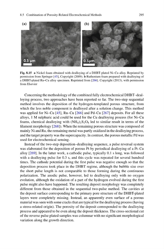
Fig. 8.15 a Nickel foam obtained with dealloying of a DHBT-plated Ni–Cu alloy. Reprinted by
permission from Springer [45], Copyright (2009). b Ruthenium foam prepared with dealloying of
a DHBT-plated Ru–Cu alloy specimen. Reprinted from [266]. Copyright (2013), with permission
from Elsevier
Concerning the methodology of the combined fully electrochemical DHBT–dealloying process, two approaches have been reported so far. The two-step sequential
method involves the deposition of the hydrogen-templated porous structure, from
which the less noble component is dealloyed after a solution change. This method
was applied for Ni–Cu [45], Ru–Cu [266] and Pd–Cu [267] deposits. For all these
alloys, 1 M sulphuric acid could be used for the Cu dealloying process (for Ni–Cu
foams, chemical dealloying with (NH 4 ) 2 S 2 O 8 led to similar result in terms of the
filament morphology [268]). When the remaining porous structure was composed of
mainly Ni and Ru, the remaining metal was partly oxidized in the dealloying process,
and the target property was the supercapacity. In contrast, the porous metallic Pd was
used for electrochemical sensing.
Instead of the two-step deposition–dealloying sequence, a pulse reversal system
was elaborated for the deposition of porous Pt by periodical dealloying of a Pt–Cu
alloy [269]. In the latter work, a cathodic pulse, typically 0.1 s long, was followed
with a dealloying pulse for 0.3 s, and this cycle was repeated for several hundred
times. The cathode potential during the first pulse was negative enough so that the
deposition process took place in the DHBT regime, although the bubble size over
the short pulse length is not comparable to those forming during the continuous
polarization. The anodic pulse, however, led to dealloying only with no oxygen
evolution, although the oxidation of a part of the hydrogen evolved during the first
pulse might also have happened. The resulting deposit morphology was completely
different from those obtained in the sequential two-pulse method. The cavities at
the deposit surface corresponding to the primary pore structure of the DHBT-plated
layers were completely missing. Instead, an apparently even surface of a porous
material was seen with some cracks that are typical for the dealloying process (having
a stress-related origin). The porosity of the deposit corresponded to the dealloying
process and appeared to be even along the deposit thickness. The cross-sectional cut
of the reverse pulse plated samples was columnar with no significant morphological
variation along the growth direction.
295
Fig. 8.15 a Nickel foam obtained with dealloying of a DHBT-plated Ni–Cu alloy. Reprinted by
permission from Springer [45], Copyright (2009). b Ruthenium foam prepared with dealloying of
a DHBT-plated Ru–Cu alloy specimen. Reprinted from [266]. Copyright (2013), with permission
from Elsevier
Concerning the methodology of the combined fully electrochemical DHBT–dealloying process, two approaches have been reported so far. The two-step sequential
method involves the deposition of the hydrogen-templated porous structure, from
which the less noble component is dealloyed after a solution change. This method
was applied for Ni–Cu [45], Ru–Cu [266] and Pd–Cu [267] deposits. For all these
alloys, 1 M sulphuric acid could be used for the Cu dealloying process (for Ni–Cu
foams, chemical dealloying with (NH 4 ) 2 S 2 O 8 led to similar result in terms of the
filament morphology [268]). When the remaining porous structure was composed of
mainly Ni and Ru, the remaining metal was partly oxidized in the dealloying process,
and the target property was the supercapacity. In contrast, the porous metallic Pd was
used for electrochemical sensing.
Instead of the two-step deposition–dealloying sequence, a pulse reversal system
was elaborated for the deposition of porous Pt by periodical dealloying of a Pt–Cu
alloy [269]. In the latter work, a cathodic pulse, typically 0.1 s long, was followed
with a dealloying pulse for 0.3 s, and this cycle was repeated for several hundred
times. The cathode potential during the first pulse was negative enough so that the
deposition process took place in the DHBT regime, although the bubble size over
the short pulse length is not comparable to those forming during the continuous
polarization. The anodic pulse, however, led to dealloying only with no oxygen
evolution, although the oxidation of a part of the hydrogen evolved during the first
pulse might also have happened. The resulting deposit morphology was completely
different from those obtained in the sequential two-pulse method. The cavities at
the deposit surface corresponding to the primary pore structure of the DHBT-plated
layers were completely missing. Instead, an apparently even surface of a porous
material was seen with some cracks that are typical for the dealloying process (having
a stress-related origin). The porosity of the deposit corresponded to the dealloying
process and appeared to be even along the deposit thickness. The cross-sectional cut
of the reverse pulse plated samples was columnar with no significant morphological
variation along the growth direction.