

170
5 Compositionally Modulated and Multilayered Deposits
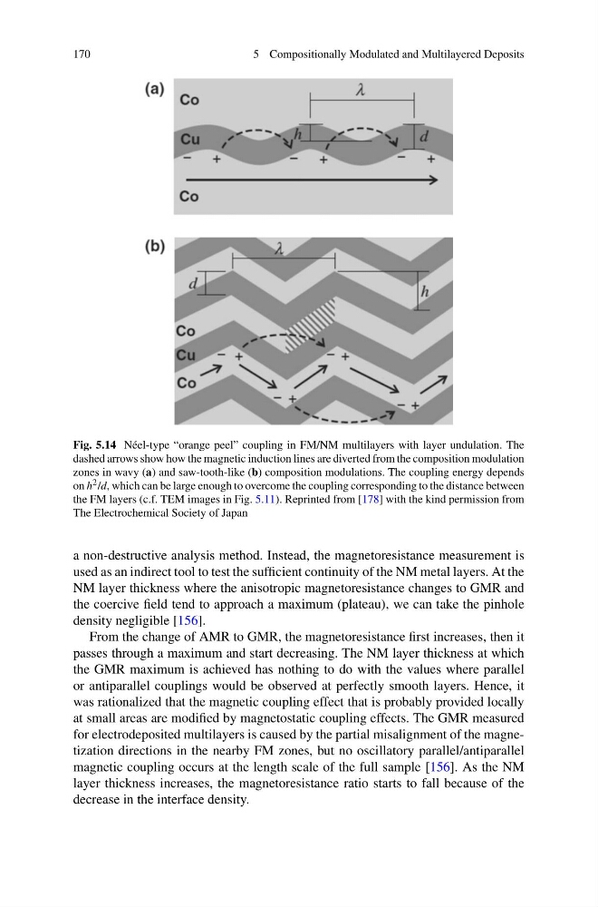
Fig. 5.14 Néel-type “orange peel” coupling in FM/NM multilayers with layer undulation. The
dashed arrows show how the magnetic induction lines are diverted from the composition modulation
zones in wavy (a) and saw-tooth-like (b) composition modulations. The coupling energy depends
on h 2 /d, which can be large enough to overcome the coupling corresponding to the distance between
the FM layers (c.f. TEM images in Fig. 5.11). Reprinted from [178] with the kind permission from
The Electrochemical Society of Japan
a non-destructive analysis method. Instead, the magnetoresistance measurement is
used as an indirect tool to test the sufficient continuity of the NM metal layers. At the
NM layer thickness where the anisotropic magnetoresistance changes to GMR and
the coercive field tend to approach a maximum (plateau), we can take the pinhole
density negligible [156].
From the change of AMR to GMR, the magnetoresistance first increases, then it
passes through a maximum and start decreasing. The NM layer thickness at which
the GMR maximum is achieved has nothing to do with the values where parallel
or antiparallel couplings would be observed at perfectly smooth layers. Hence, it
was rationalized that the magnetic coupling effect that is probably provided locally
at small areas are modified by magnetostatic coupling effects. The GMR measured
for electrodeposited multilayers is caused by the partial misalignment of the magnetization directions in the nearby FM zones, but no oscillatory parallel/antiparallel
magnetic coupling occurs at the length scale of the full sample [156]. As the NM
layer thickness increases, the magnetoresistance ratio starts to fall because of the
decrease in the interface density.
5 Compositionally Modulated and Multilayered Deposits
Fig. 5.14 Néel-type “orange peel” coupling in FM/NM multilayers with layer undulation. The
dashed arrows show how the magnetic induction lines are diverted from the composition modulation
zones in wavy (a) and saw-tooth-like (b) composition modulations. The coupling energy depends
on h 2 /d, which can be large enough to overcome the coupling corresponding to the distance between
the FM layers (c.f. TEM images in Fig. 5.11). Reprinted from [178] with the kind permission from
The Electrochemical Society of Japan
a non-destructive analysis method. Instead, the magnetoresistance measurement is
used as an indirect tool to test the sufficient continuity of the NM metal layers. At the
NM layer thickness where the anisotropic magnetoresistance changes to GMR and
the coercive field tend to approach a maximum (plateau), we can take the pinhole
density negligible [156].
From the change of AMR to GMR, the magnetoresistance first increases, then it
passes through a maximum and start decreasing. The NM layer thickness at which
the GMR maximum is achieved has nothing to do with the values where parallel
or antiparallel couplings would be observed at perfectly smooth layers. Hence, it
was rationalized that the magnetic coupling effect that is probably provided locally
at small areas are modified by magnetostatic coupling effects. The GMR measured
for electrodeposited multilayers is caused by the partial misalignment of the magnetization directions in the nearby FM zones, but no oscillatory parallel/antiparallel
magnetic coupling occurs at the length scale of the full sample [156]. As the NM
layer thickness increases, the magnetoresistance ratio starts to fall because of the
decrease in the interface density.