

150
5 Compositionally Modulated and Multilayered Deposits
5.3.4 Multilayer Formation with Transport Rate Modulation
Electrodeposition of a multilayer is possible with d.c. current if the transport rate in
the electrolyte solution is modulated. Although the lateral homogeneity can hardly be
ensured, the transport rate modulation can be carried out with the periodic operation
of a simple stirrer. A demonstration of this method showed [67] that Co–P alloys with
varying composition can be deposited by this manner. Since the flow rate around the
cathode cannot be changed instantaneously due to the finite viscosity of the solution,
sharp interface cannot be expected. The individual layer thickness achieved with this
method was a few tens of nanometres.
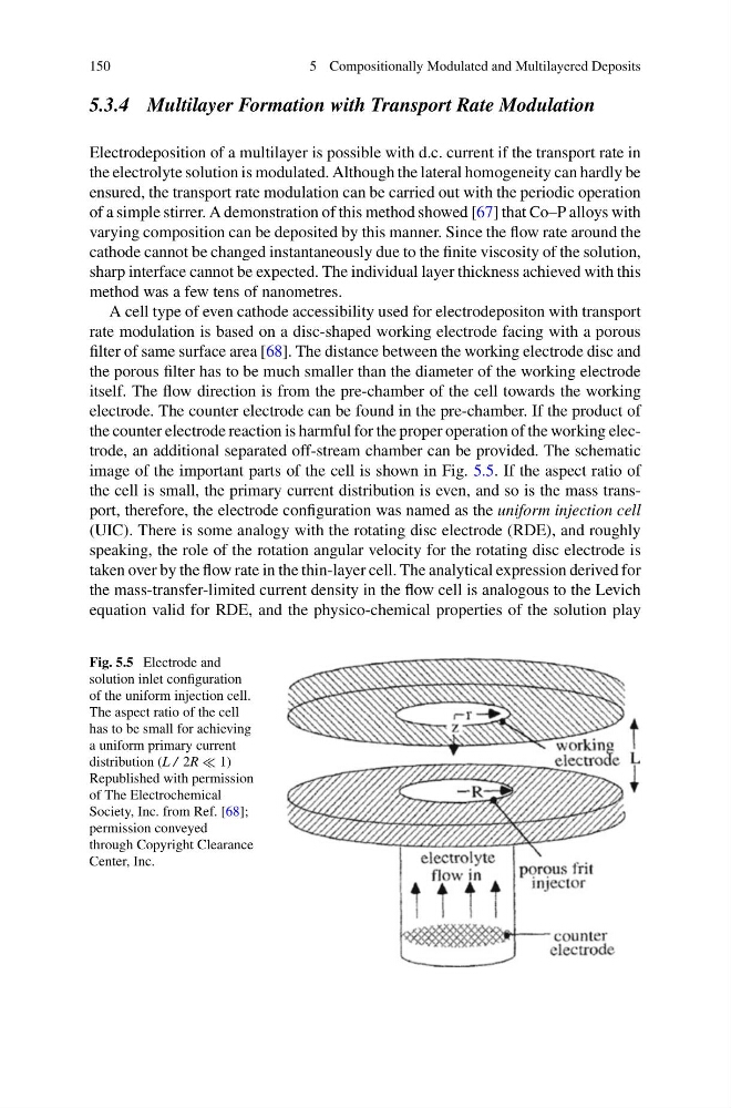
A cell type of even cathode accessibility used for electrodepositon with transport
rate modulation is based on a disc-shaped working electrode facing with a porous
filter of same surface area [68]. The distance between the working electrode disc and
the porous filter has to be much smaller than the diameter of the working electrode
itself. The flow direction is from the pre-chamber of the cell towards the working
electrode. The counter electrode can be found in the pre-chamber. If the product of
the counter electrode reaction is harmful for the proper operation of the working electrode, an additional separated off-stream chamber can be provided. The schematic
image of the important parts of the cell is shown in Fig. 5.5. If the aspect ratio of
the cell is small, the primary current distribution is even, and so is the mass transport, therefore, the electrode configuration was named as the uniform injection cell
(UIC). There is some analogy with the rotating disc electrode (RDE), and roughly
speaking, the role of the rotation angular velocity for the rotating disc electrode is
taken over by the flow rate in the thin-layer cell. The analytical expression derived for
the mass-transfer-limited current density in the flow cell is analogous to the Levich
equation valid for RDE, and the physico-chemical properties of the solution play
Fig. 5.5 Electrode and
solution inlet configuration
of the uniform injection cell.
The aspect ratio of the cell
has to be small for achieving
a uniform primary current
distribution (L / 2R 1)
Republished with permission
of The Electrochemical
Society, Inc. from Ref. [68];
permission conveyed
through Copyright Clearance
Center, Inc.
5 Compositionally Modulated and Multilayered Deposits
5.3.4 Multilayer Formation with Transport Rate Modulation
Electrodeposition of a multilayer is possible with d.c. current if the transport rate in
the electrolyte solution is modulated. Although the lateral homogeneity can hardly be
ensured, the transport rate modulation can be carried out with the periodic operation
of a simple stirrer. A demonstration of this method showed [67] that Co–P alloys with
varying composition can be deposited by this manner. Since the flow rate around the
cathode cannot be changed instantaneously due to the finite viscosity of the solution,
sharp interface cannot be expected. The individual layer thickness achieved with this
method was a few tens of nanometres.
A cell type of even cathode accessibility used for electrodepositon with transport
rate modulation is based on a disc-shaped working electrode facing with a porous
filter of same surface area [68]. The distance between the working electrode disc and
the porous filter has to be much smaller than the diameter of the working electrode
itself. The flow direction is from the pre-chamber of the cell towards the working
electrode. The counter electrode can be found in the pre-chamber. If the product of
the counter electrode reaction is harmful for the proper operation of the working electrode, an additional separated off-stream chamber can be provided. The schematic
image of the important parts of the cell is shown in Fig. 5.5. If the aspect ratio of
the cell is small, the primary current distribution is even, and so is the mass transport, therefore, the electrode configuration was named as the uniform injection cell
(UIC). There is some analogy with the rotating disc electrode (RDE), and roughly
speaking, the role of the rotation angular velocity for the rotating disc electrode is
taken over by the flow rate in the thin-layer cell. The analytical expression derived for
the mass-transfer-limited current density in the flow cell is analogous to the Levich
equation valid for RDE, and the physico-chemical properties of the solution play
Fig. 5.5 Electrode and
solution inlet configuration
of the uniform injection cell.
The aspect ratio of the cell
has to be small for achieving
a uniform primary current
distribution (L / 2R 1)
Republished with permission
of The Electrochemical
Society, Inc. from Ref. [68];
permission conveyed
through Copyright Clearance
Center, Inc.