

The Influence of the Mesh Element Size …
527
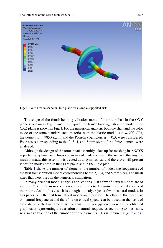
Fig. 3 Fourth mode shape in OXY plane for a simple supported disk
The shape of the fourth bending vibration mode of the rotor-shaft in the OXY
plane is shown in Fig. 3, and the shape of the fourth bending vibration mode in the
OXZ plane is shown in Fig. 4. For the numerical analysis, both the shaft and the rotor
made of the same standard steel material with the elastic modulus E = 200 GPa,
the density ρ = 7850 kg/m
3 and the Poisson coefficient μ = 0.3, were considered.
Four cases corresponding to the 2, 3, 4, and 5 mm sizes of the finite element were
analyzed.
Although the design of the rotor–shaft assembly taken up for meshing in ANSYS
is perfectly symmetrical, however, in modal analysis, due to the size and the way the
mesh is made, this assembly is treated as unsymmetrical and therefore will present
vibration modes both in the OXY plane and in the OXZ plan.
Table 1 shows the number of elements, the number of nodes, the frequencies of
the first four vibration modes corresponding to the 2, 3, 4, and 5 mm sizes, and mesh
sizes that were used in the numerical simulation.
In many practical modal analysis applications, just a few of natural modes are of
interest. One of the most common applications is to determine the critical speeds of
the rotors. And in this case, it is enough to analyze just a few of natural modes. In
this paper, only the first four natural modes are proposed. The effect of the mesh size
on natural frequencies and therefore on critical speeds can be traced on the basis of
the data presented in Table 1. At the same time, a suggestive view can be obtained
graphically representing the variation of natural frequencies according to mesh size,
so also as a function of the number of finite elements. This is shown in Figs. 5 and 6.
527
Fig. 3 Fourth mode shape in OXY plane for a simple supported disk
The shape of the fourth bending vibration mode of the rotor-shaft in the OXY
plane is shown in Fig. 3, and the shape of the fourth bending vibration mode in the
OXZ plane is shown in Fig. 4. For the numerical analysis, both the shaft and the rotor
made of the same standard steel material with the elastic modulus E = 200 GPa,
the density ρ = 7850 kg/m
3 and the Poisson coefficient μ = 0.3, were considered.
Four cases corresponding to the 2, 3, 4, and 5 mm sizes of the finite element were
analyzed.
Although the design of the rotor–shaft assembly taken up for meshing in ANSYS
is perfectly symmetrical, however, in modal analysis, due to the size and the way the
mesh is made, this assembly is treated as unsymmetrical and therefore will present
vibration modes both in the OXY plane and in the OXZ plan.
Table 1 shows the number of elements, the number of nodes, the frequencies of
the first four vibration modes corresponding to the 2, 3, 4, and 5 mm sizes, and mesh
sizes that were used in the numerical simulation.
In many practical modal analysis applications, just a few of natural modes are of
interest. One of the most common applications is to determine the critical speeds of
the rotors. And in this case, it is enough to analyze just a few of natural modes. In
this paper, only the first four natural modes are proposed. The effect of the mesh size
on natural frequencies and therefore on critical speeds can be traced on the basis of
the data presented in Table 1. At the same time, a suggestive view can be obtained
graphically representing the variation of natural frequencies according to mesh size,
so also as a function of the number of finite elements. This is shown in Figs. 5 and 6.