

510
C. Popa et al.
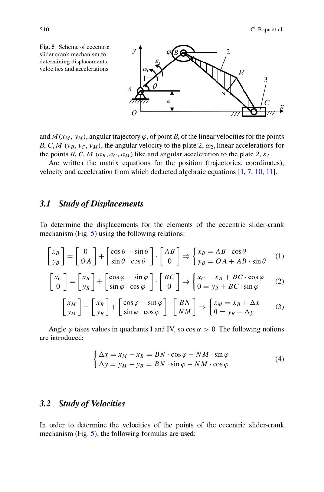
Fig. 5 Scheme of eccentric
slider-crank mechanism for
determining displacements,
velocities and accelerations
and M(x M , y M ), angular trajectory ϕ, of point B, of the linear velocities for the points
B, C, M (v B , v C , v M ), the angular velocity to the plate 2, ω 2 , linear accelerations for
the points B, C, M (a B , a C , a M ) like and angular acceleration to the plate 2, ε 2 .
Are written the matrix equations for the position (trajectories, coordinates),
velocity and acceleration from which deducted algebraic equations [1, 7, 10, 11].
3.1 Study of Displacements
To determine the displacements for the elements of the eccentric slider-crank
mechanism (Fig. 5) using the following relations:
x B
y B
=
0
O A
+
cos θ − sin θ
sin θ cos θ
·
AB
0
⇒
x B = AB · cos θ
y B = O A + AB · sin θ
(1)
x C
0
=
x B
y B
+
cos ϕ − sin ϕ
sin ϕ cos ϕ
·
BC
0
⇒
x C = x B + BC · cos ϕ
0 = y B + BC · sin ϕ
(2)
x M
y M
=
x B
y B
+
cos ϕ − sin ϕ
sin ϕ cos ϕ
·
B N
N M
⇒
x M = x B +
0 = y B +
(3)
Angle ϕ takes values in quadrants I and IV, so cos α > 0. The following notions
are introduced:
= x M − x B = B N · cos ϕ − N M · sin ϕ
= y M − y B = B N · sin ϕ − N M · cos ϕ
(4)
3.2 Study of Velocities
In order to determine the velocities of the points of the eccentric slider-crank
mechanism (Fig. 5), the following formulas are used:
C. Popa et al.
Fig. 5 Scheme of eccentric
slider-crank mechanism for
determining displacements,
velocities and accelerations
and M(x M , y M ), angular trajectory ϕ, of point B, of the linear velocities for the points
B, C, M (v B , v C , v M ), the angular velocity to the plate 2, ω 2 , linear accelerations for
the points B, C, M (a B , a C , a M ) like and angular acceleration to the plate 2, ε 2 .
Are written the matrix equations for the position (trajectories, coordinates),
velocity and acceleration from which deducted algebraic equations [1, 7, 10, 11].
3.1 Study of Displacements
To determine the displacements for the elements of the eccentric slider-crank
mechanism (Fig. 5) using the following relations:
x B
y B
=
0
O A
+
cos θ − sin θ
sin θ cos θ
·
AB
0
⇒
x B = AB · cos θ
y B = O A + AB · sin θ
(1)
x C
0
=
x B
y B
+
cos ϕ − sin ϕ
sin ϕ cos ϕ
·
BC
0
⇒
x C = x B + BC · cos ϕ
0 = y B + BC · sin ϕ
(2)
x M
y M
=
x B
y B
+
cos ϕ − sin ϕ
sin ϕ cos ϕ
·
B N
N M
⇒
x M = x B +
0 = y B +
(3)
Angle ϕ takes values in quadrants I and IV, so cos α > 0. The following notions
are introduced:
= x M − x B = B N · cos ϕ − N M · sin ϕ
= y M − y B = B N · sin ϕ − N M · cos ϕ
(4)
3.2 Study of Velocities
In order to determine the velocities of the points of the eccentric slider-crank
mechanism (Fig. 5), the following formulas are used: