

Composed Isolation System Concept for Vibration Effects Mitigation …
479
The case of the free movement on the supports can be written in the relation for
the effective vibration period
T e f
based on the relation obtained for the effective
stiffness as follows [5]:
T e f = 2π
P
k e f · g
(12)
T e f = 2π
P
P
1
R
+
μ
u
· g
= 2π
R · u
(u + μ · R) · g
(13)
4 Numerical Analysis on Pendulum System Parameter
Operation
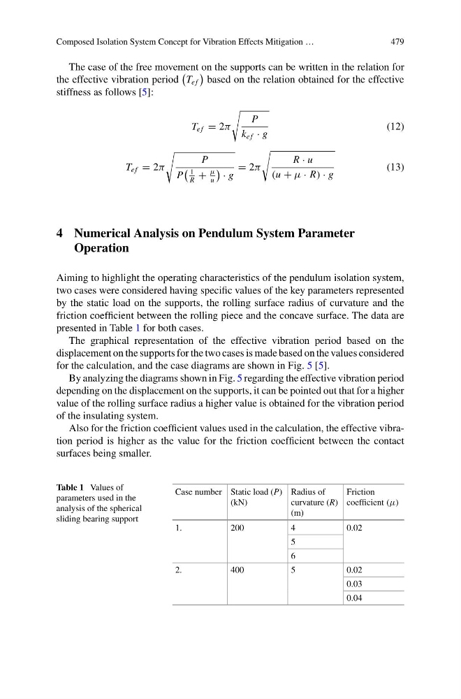
Aiming to highlight the operating characteristics of the pendulum isolation system,
two cases were considered having specific values of the key parameters represented
by the static load on the supports, the rolling surface radius of curvature and the
friction coefficient between the rolling piece and the concave surface. The data are
presented in Table 1 for both cases.
The graphical representation of the effective vibration period based on the
displacement on the supports for the two cases is made based on the values considered
for the calculation, and the case diagrams are shown in Fig. 5 [5].
By analyzing the diagrams shown in Fig. 5 regarding the effective vibration period
depending on the displacement on the supports, it can be pointed out that for a higher
value of the rolling surface radius a higher value is obtained for the vibration period
of the insulating system.
Also for the friction coefficient values used in the calculation, the effective vibration period is higher as the value for the friction coefficient between the contact
surfaces being smaller.
Table 1 Values of
parameters used in the
analysis of the spherical
sliding bearing support
Case number Static load (P)
(kN)
Radius of
curvature (R)
(m)
Friction
coefficient (μ)
1.
200
4
0.02
5
6
2.
400
5
0.02
0.03
0.04
479
The case of the free movement on the supports can be written in the relation for
the effective vibration period
T e f
based on the relation obtained for the effective
stiffness as follows [5]:
T e f = 2π
P
k e f · g
(12)
T e f = 2π
P
P
1
R
+
μ
u
· g
= 2π
R · u
(u + μ · R) · g
(13)
4 Numerical Analysis on Pendulum System Parameter
Operation
Aiming to highlight the operating characteristics of the pendulum isolation system,
two cases were considered having specific values of the key parameters represented
by the static load on the supports, the rolling surface radius of curvature and the
friction coefficient between the rolling piece and the concave surface. The data are
presented in Table 1 for both cases.
The graphical representation of the effective vibration period based on the
displacement on the supports for the two cases is made based on the values considered
for the calculation, and the case diagrams are shown in Fig. 5 [5].
By analyzing the diagrams shown in Fig. 5 regarding the effective vibration period
depending on the displacement on the supports, it can be pointed out that for a higher
value of the rolling surface radius a higher value is obtained for the vibration period
of the insulating system.
Also for the friction coefficient values used in the calculation, the effective vibration period is higher as the value for the friction coefficient between the contact
surfaces being smaller.
Table 1 Values of
parameters used in the
analysis of the spherical
sliding bearing support
Case number Static load (P)
(kN)
Radius of
curvature (R)
(m)
Friction
coefficient (μ)
1.
200
4
0.02
5
6
2.
400
5
0.02
0.03
0.04