

464
M. Dutkiewicz and M. R. Machado
conductor. High amplitudes are observed in the vertical plane, whereas the frequencies depend on the type of a conductor and vibrations [4, 10]. Galloping is a typical
instability caused by the coupling of aerodynamic forces which affect the conductor
with its vibrations. Conductor vibrations change the wind angle of attack on a periodic basis. The change of the angle of attack results in a change of aerodynamic forces
affecting the conductor, which consequently changes the conductor response. The
first, simplified criterion (if a single degree-of-freedom system is applied) pertaining
to the instability connected with galloping was presented by Den Hartog [11] and
developed by other researchers [10]. A precondition for galloping (on the basis of the
quasi-steady theory) is the presence of negative aero-elastic damping in the system.
A conductor of a circular section cannot gallop due to its geometrical symmetry
(dCL/dα = 0), unless this section is changed. Icing of a conductor changes its cross
section; thus, it leads to its aerodynamic instability [10]. Research works carried out
by Den Hartog indicate that the aerodynamic instability is the main reason for the
galloping phenomenon. Further research proved that the torsion motion is an integral part of the galloping phenomenon. The effect of a coupled torsion–translational
motion plays a crucial role in most cases of progressing galloping [12].
These extremely important phenomena described above have mobilized the
authors of the article to look for transmission line vibration solutions using numerical
methods. Spectral element method (SEM) proved to be such a method, where the
exact dynamic shape functions are used in the solution. The use of SEM is very wide:
in composites [13, 14] and in damage detection [15–18].
2 Mathematical Model of Overhead Transmission Line
The cable model meets the differential equation presented in the form [19–21]
E I
∂
4
v(x, t)
∂ x 4 − T
∂
2
v(x, t)
∂ x 2 + ρ A
∂
2
v(x, t)
∂t 2
= 0
( 1 )
where ρ A—mass per unit length, E I —the uniform bending rigidity, T is tension
force, v(x, t)—the cable displacement.
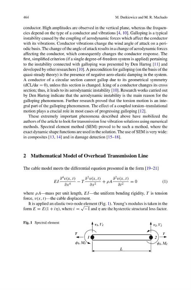
It is applied an elastic two-node element (Fig. 1). Young’s modulus is taken in the
form E = E(1 + iη), where i =
√
−1 and η are the hysteretic structural loss factor.
Fig. 1 Spectral element
M. Dutkiewicz and M. R. Machado
conductor. High amplitudes are observed in the vertical plane, whereas the frequencies depend on the type of a conductor and vibrations [4, 10]. Galloping is a typical
instability caused by the coupling of aerodynamic forces which affect the conductor
with its vibrations. Conductor vibrations change the wind angle of attack on a periodic basis. The change of the angle of attack results in a change of aerodynamic forces
affecting the conductor, which consequently changes the conductor response. The
first, simplified criterion (if a single degree-of-freedom system is applied) pertaining
to the instability connected with galloping was presented by Den Hartog [11] and
developed by other researchers [10]. A precondition for galloping (on the basis of the
quasi-steady theory) is the presence of negative aero-elastic damping in the system.
A conductor of a circular section cannot gallop due to its geometrical symmetry
(dCL/dα = 0), unless this section is changed. Icing of a conductor changes its cross
section; thus, it leads to its aerodynamic instability [10]. Research works carried out
by Den Hartog indicate that the aerodynamic instability is the main reason for the
galloping phenomenon. Further research proved that the torsion motion is an integral part of the galloping phenomenon. The effect of a coupled torsion–translational
motion plays a crucial role in most cases of progressing galloping [12].
These extremely important phenomena described above have mobilized the
authors of the article to look for transmission line vibration solutions using numerical
methods. Spectral element method (SEM) proved to be such a method, where the
exact dynamic shape functions are used in the solution. The use of SEM is very wide:
in composites [13, 14] and in damage detection [15–18].
2 Mathematical Model of Overhead Transmission Line
The cable model meets the differential equation presented in the form [19–21]
E I
∂
4
v(x, t)
∂ x 4 − T
∂
2
v(x, t)
∂ x 2 + ρ A
∂
2
v(x, t)
∂t 2
= 0
( 1 )
where ρ A—mass per unit length, E I —the uniform bending rigidity, T is tension
force, v(x, t)—the cable displacement.
It is applied an elastic two-node element (Fig. 1). Young’s modulus is taken in the
form E = E(1 + iη), where i =
√
−1 and η are the hysteretic structural loss factor.
Fig. 1 Spectral element