

Vibroacoustic Diagnostics …
417
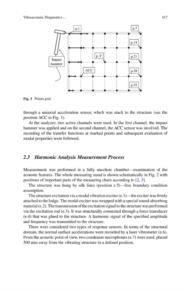
Fig. 1 Points grid
through a uniaxial acceleration sensor, which was stuck to the structure (see the
position ACC in Fig. 1).
At the analyzer, two active channels were used. In the first channel, the impact
hammer was applied and on the second channel, the ACC sensor was involved. The
recording of the transfer functions at marked points and subsequent evaluation of
modal properties were followed.
2.3 Harmonic Analysis Measurement Process
Measurement was performed in a fully anechoic chamber—examination of the
acoustic features. The whole measuring stand is shown schematically in Fig. 2 with
positions of important parts of the measuring chain according to [2, 3].
The structure was hung by silk lines (position e.5)—free boundary condition
assumption.
The structure excitation via a modal vibration exciter (e.1)—the exciter was firmly
attached to the lodge. The modal exciter was wrapped with a special sound-absorbing
material (e.2). The transmission of the excitation signal to the structure was performed
via the excitation rod (e.3). It was structurally connected through a force transducer
(e.4) that was glued to the structure. A harmonic signal of the specified amplitude
and frequency was transmitted to the structure.
There were considered two types of response sensors. In terms of the structural
domain, the normal surface accelerations were recorded by a laser vibrometer (e.6).
From the acoustic point of view, two condenser microphones (e.7) were used, placed
500 mm away from the vibrating structure in a defined position.
417
Fig. 1 Points grid
through a uniaxial acceleration sensor, which was stuck to the structure (see the
position ACC in Fig. 1).
At the analyzer, two active channels were used. In the first channel, the impact
hammer was applied and on the second channel, the ACC sensor was involved. The
recording of the transfer functions at marked points and subsequent evaluation of
modal properties were followed.
2.3 Harmonic Analysis Measurement Process
Measurement was performed in a fully anechoic chamber—examination of the
acoustic features. The whole measuring stand is shown schematically in Fig. 2 with
positions of important parts of the measuring chain according to [2, 3].
The structure was hung by silk lines (position e.5)—free boundary condition
assumption.
The structure excitation via a modal vibration exciter (e.1)—the exciter was firmly
attached to the lodge. The modal exciter was wrapped with a special sound-absorbing
material (e.2). The transmission of the excitation signal to the structure was performed
via the excitation rod (e.3). It was structurally connected through a force transducer
(e.4) that was glued to the structure. A harmonic signal of the specified amplitude
and frequency was transmitted to the structure.
There were considered two types of response sensors. In terms of the structural
domain, the normal surface accelerations were recorded by a laser vibrometer (e.6).
From the acoustic point of view, two condenser microphones (e.7) were used, placed
500 mm away from the vibrating structure in a defined position.