

346
A. Gerocs et al.
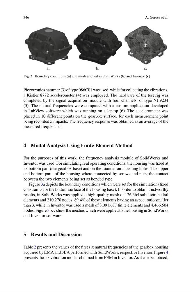
Fig. 3 Boundary conditions (a) and mesh applied in SolidWorks (b) and Inventor (c)
Piezotronics hammer (3) of type 086C01 was used, while for collecting the vibrations,
a Kistler 8772 accelerometer (4) was employed. The hardware of the test rig was
completed by the signal acquisition module with four channels, of type NI 9234
(5). The natural frequencies were computed with a custom application developed
in LabView software which was running on a laptop (6). The accelerometer was
placed in 10 different points on the gearbox surface, for each measurement point
being recorded 5 impacts. The frequency response was obtained as an average of the
measured frequencies.
4 Modal Analysis Using Finite Element Method
For the purposes of this work, the frequency analysis module of SolidWorks and
Inventor was used. For simulating real operating conditions, the housing was fixed at
its bottom part (the gearbox base) and on the foundation fastening holes. The upper
and bottom parts of the housing where connected by screws and nuts, the contact
between the two elements being set as bonded type.
Figure 3a depicts the boundary conditions which were set for the simulation (fixed
constraints for the bottom surface of the housing base). In order to obtain trustworthy
results, in SolidWorks was applied a high-quality mesh of 126,364 solid tetrahedral
elements and 210,270 nodes, 89.4% of these elements having an aspect ratio smaller
than 3, while in Inventor was used a mesh of 3,091,677 finite elements and 4,466,504
nodes. Figure 3b, c show the meshes which were applied to the housing in SolidWorks
and Inventor software.
5 Results and Discussion
Table 2 presents the values of the first six natural frequencies of the gearbox housing
acquired by EMA and FEA performed with SolidWorks, respective Inventor. Figure 4
presents the six vibration modes obtained from FEM in Inventor. As it can be noticed,
A. Gerocs et al.
Fig. 3 Boundary conditions (a) and mesh applied in SolidWorks (b) and Inventor (c)
Piezotronics hammer (3) of type 086C01 was used, while for collecting the vibrations,
a Kistler 8772 accelerometer (4) was employed. The hardware of the test rig was
completed by the signal acquisition module with four channels, of type NI 9234
(5). The natural frequencies were computed with a custom application developed
in LabView software which was running on a laptop (6). The accelerometer was
placed in 10 different points on the gearbox surface, for each measurement point
being recorded 5 impacts. The frequency response was obtained as an average of the
measured frequencies.
4 Modal Analysis Using Finite Element Method
For the purposes of this work, the frequency analysis module of SolidWorks and
Inventor was used. For simulating real operating conditions, the housing was fixed at
its bottom part (the gearbox base) and on the foundation fastening holes. The upper
and bottom parts of the housing where connected by screws and nuts, the contact
between the two elements being set as bonded type.
Figure 3a depicts the boundary conditions which were set for the simulation (fixed
constraints for the bottom surface of the housing base). In order to obtain trustworthy
results, in SolidWorks was applied a high-quality mesh of 126,364 solid tetrahedral
elements and 210,270 nodes, 89.4% of these elements having an aspect ratio smaller
than 3, while in Inventor was used a mesh of 3,091,677 finite elements and 4,466,504
nodes. Figure 3b, c show the meshes which were applied to the housing in SolidWorks
and Inventor software.
5 Results and Discussion
Table 2 presents the values of the first six natural frequencies of the gearbox housing
acquired by EMA and FEA performed with SolidWorks, respective Inventor. Figure 4
presents the six vibration modes obtained from FEM in Inventor. As it can be noticed,