

Development of Methodologies and Means for Noise Protection …
123
walls and the ceiling in the workshop were determined so that the noise level of
94 dB(A) in the machine room is reduced to 47 dB(A) in front of the building
[12];
• noise protection curtain for a scrapyard with car crushers close to a suburban area
of a Serbian City (Užice); application of the noise protection mean reduced the
noise level in the control point on the border of the residential area from 53.1 to
51.2 dB(A) and the calculate noise map. Figure 3 shows that the level of the noise
within the residential area is less than 50 dB [13];
• acoustic treatment of a mechanical workshop with seven machines that generated
cumulative noise levels of 94.4 dB(A); by covering all of the open surfaces of
the workshop (walls, floors and ceilings) with sound absorption materials, the
noise level was reduced to 87.7 dB(A), which is sufficient to allow permanent
exposition to noise in periods less than 6 h [51];
The project was also developed and three measurement systems for the characterization of materials by sound absorption, transmission or emission:
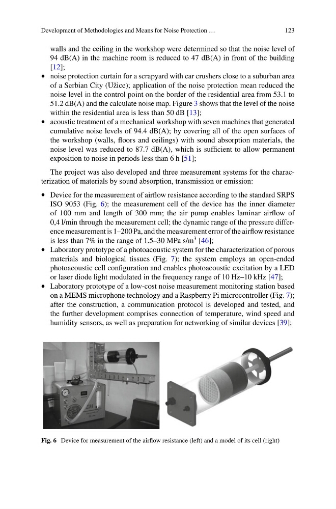
• Device for the measurement of airflow resistance according to the standard SRPS
ISO 9053 (Fig. 6); the measurement cell of the device has the inner diameter
of 100 mm and length of 300 mm; the air pump enables laminar airflow of
0,4 l/min through the measurement cell; the dynamic range of the pressure difference measurement is 1–200 Pa, and the measurement error of the airflow resistance
is less than 7% in the range of 1.5–30 MPa s/m
3 [46];
• Laboratory prototype of a photoacoustic system for the characterization of porous
materials and biological tissues (Fig. 7); the system employs an open-ended
photoacoustic cell configuration and enables photoacoustic excitation by a LED
or laser diode light modulated in the frequency range of 10 Hz–10 kHz [47];
• Laboratory prototype of a low-cost noise measurement monitoring station based
on a MEMS microphone technology and a Raspberry Pi microcontroller (Fig. 7);
after the construction, a communication protocol is developed and tested, and
the further development comprises connection of temperature, wind speed and
humidity sensors, as well as preparation for networking of similar devices [39];
Fig. 6 Device for measurement of the airflow resistance (left) and a model of its cell (right)
123
walls and the ceiling in the workshop were determined so that the noise level of
94 dB(A) in the machine room is reduced to 47 dB(A) in front of the building
[12];
• noise protection curtain for a scrapyard with car crushers close to a suburban area
of a Serbian City (Užice); application of the noise protection mean reduced the
noise level in the control point on the border of the residential area from 53.1 to
51.2 dB(A) and the calculate noise map. Figure 3 shows that the level of the noise
within the residential area is less than 50 dB [13];
• acoustic treatment of a mechanical workshop with seven machines that generated
cumulative noise levels of 94.4 dB(A); by covering all of the open surfaces of
the workshop (walls, floors and ceilings) with sound absorption materials, the
noise level was reduced to 87.7 dB(A), which is sufficient to allow permanent
exposition to noise in periods less than 6 h [51];
The project was also developed and three measurement systems for the characterization of materials by sound absorption, transmission or emission:
• Device for the measurement of airflow resistance according to the standard SRPS
ISO 9053 (Fig. 6); the measurement cell of the device has the inner diameter
of 100 mm and length of 300 mm; the air pump enables laminar airflow of
0,4 l/min through the measurement cell; the dynamic range of the pressure difference measurement is 1–200 Pa, and the measurement error of the airflow resistance
is less than 7% in the range of 1.5–30 MPa s/m
3 [46];
• Laboratory prototype of a photoacoustic system for the characterization of porous
materials and biological tissues (Fig. 7); the system employs an open-ended
photoacoustic cell configuration and enables photoacoustic excitation by a LED
or laser diode light modulated in the frequency range of 10 Hz–10 kHz [47];
• Laboratory prototype of a low-cost noise measurement monitoring station based
on a MEMS microphone technology and a Raspberry Pi microcontroller (Fig. 7);
after the construction, a communication protocol is developed and tested, and
the further development comprises connection of temperature, wind speed and
humidity sensors, as well as preparation for networking of similar devices [39];
Fig. 6 Device for measurement of the airflow resistance (left) and a model of its cell (right)