

84 The Bennett linkage
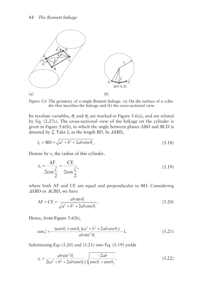
Its revolute variables, θ 1 and θ 2 are marked in Figure 5.6(a), and are related
by Eq. (2.27c). The cross- sectional view of the linkage on the cylinder is
given in Figure 5.6(b), in which the angle between planes ABD and BCD is
denoted by ξ. Take l 0 as the length BD. In ΔABD,
.
(5.18)
Denote by r 0 the radius of this cylinder.
,
(5.19)
where both AF and CE are equal and perpendicular to BD. Considering
ΔABD or ΔCBD, we have
.
(5.20)
Hence, from Figure 5.6(b),
.
(5.21)
Substituting Eqs (5.20) and (5.21) into Eq. (5.19) yields
.
(5.22)
(a)
(b)
Figure 5.6 The geometry of a single Bennett linkage. (a) On the surface of a cylinder that inscribes the linkage and (b) the cross-sectional view.
Its revolute variables, θ 1 and θ 2 are marked in Figure 5.6(a), and are related
by Eq. (2.27c). The cross- sectional view of the linkage on the cylinder is
given in Figure 5.6(b), in which the angle between planes ABD and BCD is
denoted by ξ. Take l 0 as the length BD. In ΔABD,
.
(5.18)
Denote by r 0 the radius of this cylinder.
,
(5.19)
where both AF and CE are equal and perpendicular to BD. Considering
ΔABD or ΔCBD, we have
.
(5.20)
Hence, from Figure 5.6(b),
.
(5.21)
Substituting Eqs (5.20) and (5.21) into Eq. (5.19) yields
.
(5.22)
(a)
(b)
Figure 5.6 The geometry of a single Bennett linkage. (a) On the surface of a cylinder that inscribes the linkage and (b) the cross-sectional view.