

Layouts of spatial motion structures 147
Figure 7.9(b), O 1 , O 3 and O 5 move upwards together, whereas O 2 , O 4 and
O 6 move downwards together.
7.3.3 Case II
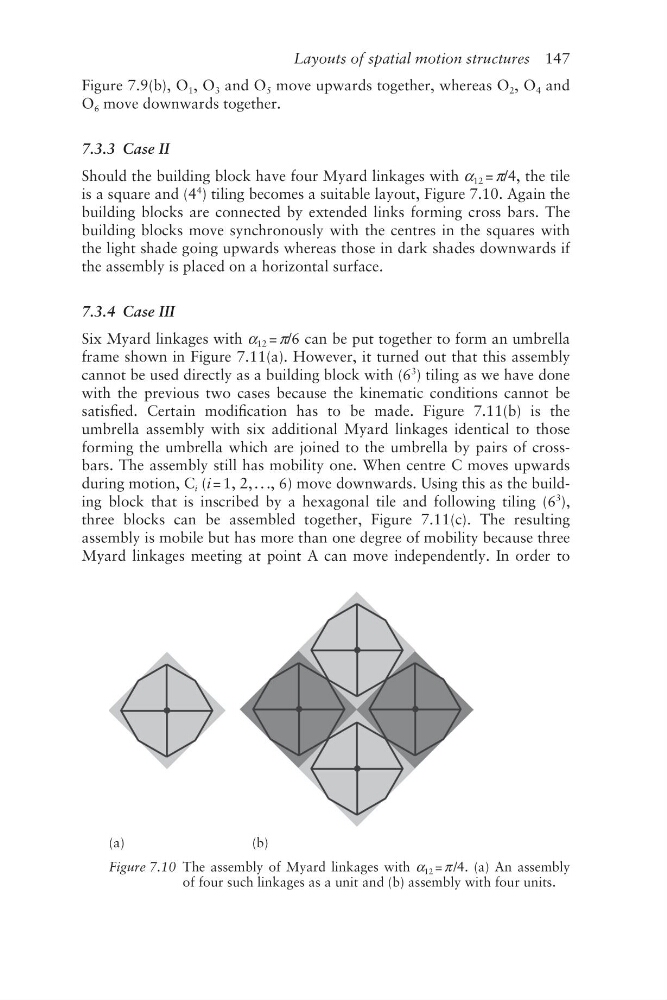
Should the building block have four Myard linkages with α 12 = π/4, the tile
is a square and (4
4
) tiling becomes a suitable layout, Figure 7.10. Again the
building blocks are connected by extended links forming cross bars. The
building blocks move synchronously with the centres in the squares with
the light shade going upwards whereas those in dark shades downwards if
the assembly is placed on a horizontal surface.
7.3.4 Case III
Six Myard linkages with α 12 = π/6 can be put together to form an umbrella
frame shown in Figure 7.11(a). However, it turned out that this assembly
cannot be used directly as a building block with (6
3
) tiling as we have done
with the previous two cases because the kinematic conditions cannot be
satisfied. Certain modification has to be made. Figure 7.11(b) is the
umbrella assembly with six additional Myard linkages identical to those
forming the umbrella which are joined to the umbrella by pairs of crossbars. The assembly still has mobility one. When centre C moves upwards
during motion, C i (i = 1, 2, . . ., 6) move downwards. Using this as the building block that is inscribed by a hexagonal tile and following tiling (6
3
),
three blocks can be assembled together, Figure 7.11(c). The resulting
assembly is mobile but has more than one degree of mobility because three
Myard linkages meeting at point A can move independently. In order to
(a)
(b)
Figure 7.10 The assembly of Myard linkages with α 12 = π /4. (a) An assembly
of four such linkages as a unit and (b) assembly with four units.
Figure 7.9(b), O 1 , O 3 and O 5 move upwards together, whereas O 2 , O 4 and
O 6 move downwards together.
7.3.3 Case II
Should the building block have four Myard linkages with α 12 = π/4, the tile
is a square and (4
4
) tiling becomes a suitable layout, Figure 7.10. Again the
building blocks are connected by extended links forming cross bars. The
building blocks move synchronously with the centres in the squares with
the light shade going upwards whereas those in dark shades downwards if
the assembly is placed on a horizontal surface.
7.3.4 Case III
Six Myard linkages with α 12 = π/6 can be put together to form an umbrella
frame shown in Figure 7.11(a). However, it turned out that this assembly
cannot be used directly as a building block with (6
3
) tiling as we have done
with the previous two cases because the kinematic conditions cannot be
satisfied. Certain modification has to be made. Figure 7.11(b) is the
umbrella assembly with six additional Myard linkages identical to those
forming the umbrella which are joined to the umbrella by pairs of crossbars. The assembly still has mobility one. When centre C moves upwards
during motion, C i (i = 1, 2, . . ., 6) move downwards. Using this as the building block that is inscribed by a hexagonal tile and following tiling (6
3
),
three blocks can be assembled together, Figure 7.11(c). The resulting
assembly is mobile but has more than one degree of mobility because three
Myard linkages meeting at point A can move independently. In order to
(a)
(b)
Figure 7.10 The assembly of Myard linkages with α 12 = π /4. (a) An assembly
of four such linkages as a unit and (b) assembly with four units.