

Layouts of spatial motion structures 139
7.2 Layouts for the Bennett linkage
7.2.1 Case I
A single Bennett linkage consisting of four links can be represented schema tically by a square as in Chapter 5. When it is used as a building block
inscribed by a square of identical orientation, tiling (4
4
) in Figure 7.1(b)
presents the simplest way to form an assembly in which other Bennett linkages are connected to each of its sides completing a layout shown in Figure
7.3(a).
The kinematics of the assembly can be examined by first considering
two adjacent Bennett linkages ABCD and DCEF, Figure 7.3. Without other
(e)
(f)
(g)
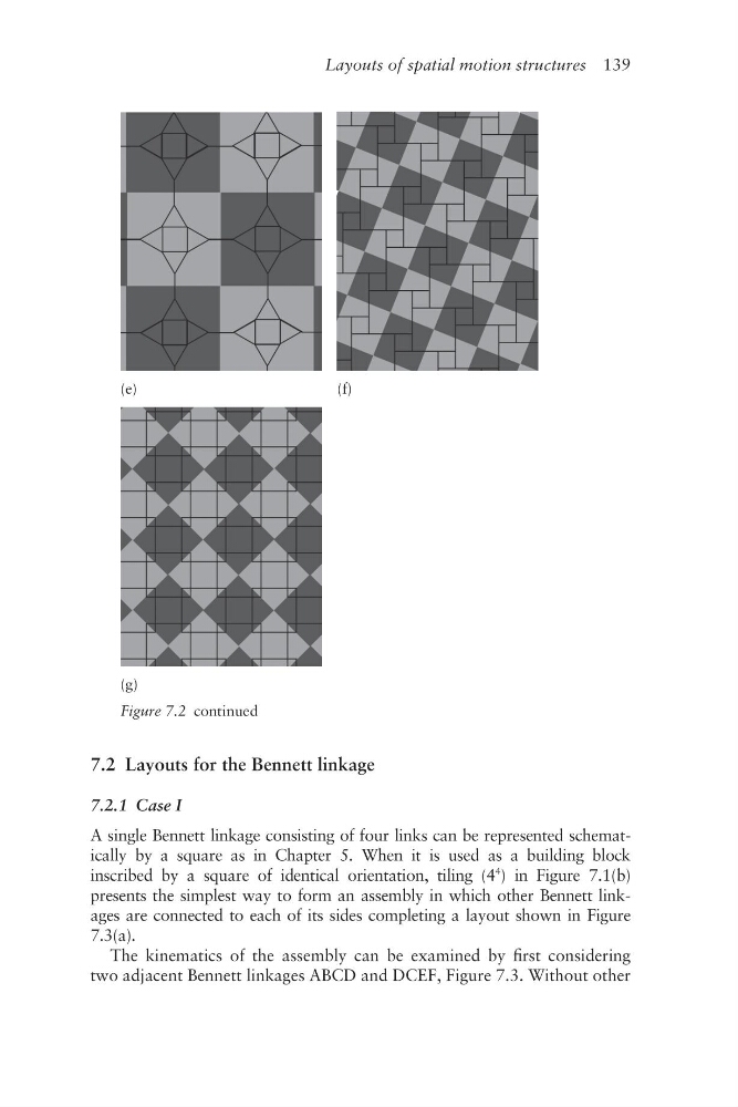
Figure 7.2 continued
7.2 Layouts for the Bennett linkage
7.2.1 Case I
A single Bennett linkage consisting of four links can be represented schema tically by a square as in Chapter 5. When it is used as a building block
inscribed by a square of identical orientation, tiling (4
4
) in Figure 7.1(b)
presents the simplest way to form an assembly in which other Bennett linkages are connected to each of its sides completing a layout shown in Figure
7.3(a).
The kinematics of the assembly can be examined by first considering
two adjacent Bennett linkages ABCD and DCEF, Figure 7.3. Without other
(e)
(f)
(g)
Figure 7.2 continued