

122 The Bricard linkages
is referred to as a pair of crossbars. It behaves like a pair of scissors. But it
is different from the scissor- like elements introduced in Chapters 3 and 4
for the axes of the end and mid hinges of a crossbar may not be parallel.
The basic element for building a large mobile assembly is formed by having
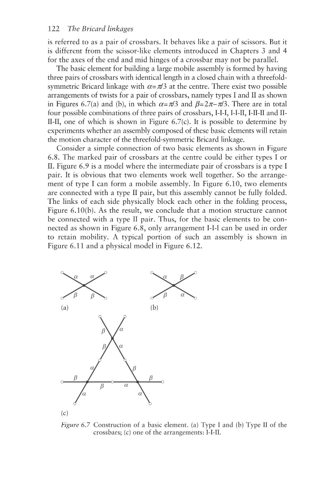
three pairs of crossbars with identical length in a closed chain with a threefoldsymmetric Bricard linkage with α = π/3 at the centre. There exist two possible
arrangements of twists for a pair of crossbars, namely types I and II as shown
in Figures 6.7(a) and (b), in which α = π/3 and β = 2π – π/3. There are in total
four possible combinations of three pairs of crossbars, I- I-I, I- I-II, I- II-II and IIII-II, one of which is shown in Figure 6.7(c). It is possible to determine by
experiments whether an assembly composed of these basic elements will retain
the motion character of the threefold- symmetric Bricard linkage.
Consider a simple connection of two basic elements as shown in Figure
6.8. The marked pair of crossbars at the centre could be either types I or
II. Figure 6.9 is a model where the intermediate pair of crossbars is a type I
pair. It is obvious that two elements work well together. So the arrangement of type I can form a mobile assembly. In Figure 6.10, two elements
are connected with a type II pair, but this assembly cannot be fully folded.
The links of each side physically block each other in the folding process,
Figure 6.10(b). As the result, we conclude that a motion structure cannot
be connected with a type II pair. Thus, for the basic elements to be connected as shown in Figure 6.8, only arrangement I- I-I can be used in order
to retain mobility. A typical portion of such an assembly is shown in
Figure 6.11 and a physical model in Figure 6.12.
(a)
(b)
(c)
Figure 6.7 Construction of a basic element. (a) Type I and (b) Type II of the
crossbars; (c) one of the arrangements: I-I-II.
is referred to as a pair of crossbars. It behaves like a pair of scissors. But it
is different from the scissor- like elements introduced in Chapters 3 and 4
for the axes of the end and mid hinges of a crossbar may not be parallel.
The basic element for building a large mobile assembly is formed by having
three pairs of crossbars with identical length in a closed chain with a threefoldsymmetric Bricard linkage with α = π/3 at the centre. There exist two possible
arrangements of twists for a pair of crossbars, namely types I and II as shown
in Figures 6.7(a) and (b), in which α = π/3 and β = 2π – π/3. There are in total
four possible combinations of three pairs of crossbars, I- I-I, I- I-II, I- II-II and IIII-II, one of which is shown in Figure 6.7(c). It is possible to determine by
experiments whether an assembly composed of these basic elements will retain
the motion character of the threefold- symmetric Bricard linkage.
Consider a simple connection of two basic elements as shown in Figure
6.8. The marked pair of crossbars at the centre could be either types I or
II. Figure 6.9 is a model where the intermediate pair of crossbars is a type I
pair. It is obvious that two elements work well together. So the arrangement of type I can form a mobile assembly. In Figure 6.10, two elements
are connected with a type II pair, but this assembly cannot be fully folded.
The links of each side physically block each other in the folding process,
Figure 6.10(b). As the result, we conclude that a motion structure cannot
be connected with a type II pair. Thus, for the basic elements to be connected as shown in Figure 6.8, only arrangement I- I-I can be used in order
to retain mobility. A typical portion of such an assembly is shown in
Figure 6.11 and a physical model in Figure 6.12.
(a)
(b)
(c)
Figure 6.7 Construction of a basic element. (a) Type I and (b) Type II of the
crossbars; (c) one of the arrangements: I-I-II.