

116 The Bennett linkage
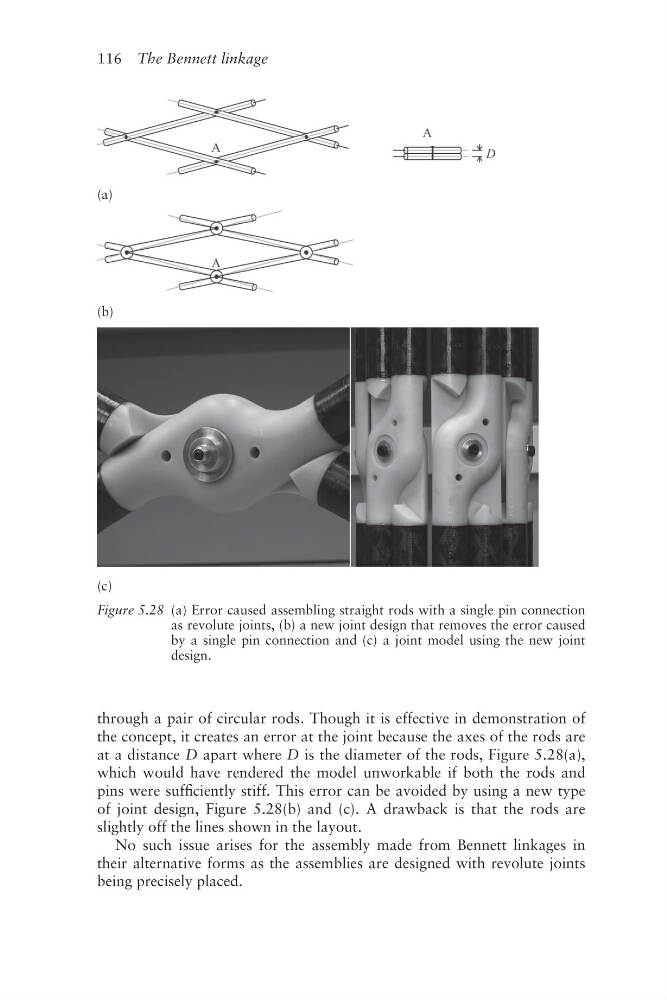
through a pair of circular rods. Though it is effective in demonstration of
the concept, it creates an error at the joint because the axes of the rods are
at a distance D apart where D is the diameter of the rods, Figure 5.28(a),
which would have rendered the model unworkable if both the rods and
pins were sufficiently stiff. This error can be avoided by using a new type
of joint design, Figure 5.28(b) and (c). A drawback is that the rods are
slightly off the lines shown in the layout.
No such issue arises for the assembly made from Bennett linkages in
their alternative forms as the assemblies are designed with revolute joints
being precisely placed.
(a)
(b)
(c)
Figure 5.28 (a) Error caused assembling straight rods with a single pin connection
as revolute joints, (b) a new joint design that removes the error caused
by a single pin connection and (c) a joint model using the new joint
design.
through a pair of circular rods. Though it is effective in demonstration of
the concept, it creates an error at the joint because the axes of the rods are
at a distance D apart where D is the diameter of the rods, Figure 5.28(a),
which would have rendered the model unworkable if both the rods and
pins were sufficiently stiff. This error can be avoided by using a new type
of joint design, Figure 5.28(b) and (c). A drawback is that the rods are
slightly off the lines shown in the layout.
No such issue arises for the assembly made from Bennett linkages in
their alternative forms as the assemblies are designed with revolute joints
being precisely placed.
(a)
(b)
(c)
Figure 5.28 (a) Error caused assembling straight rods with a single pin connection
as revolute joints, (b) a new joint design that removes the error caused
by a single pin connection and (c) a joint model using the new joint
design.