

Appendix A
147
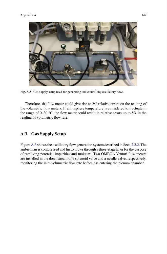
Fig. A.3 Gas supply setup used for generating and controlling oscillatory flows
Therefore, the flow meter could give rise to 2% relative errors on the reading of
the volumetric flow meters. If atmosphere temperature is considered to fluctuate in
the range of 0–30 °C, the flow meter could result in relative errors up to 5% in the
reading of volumetric flow rate.
A.3 Gas Supply Setup
Figure A.3 shows the oscillatory flow generation system described in Sect. 2.2.2. The
ambient air is compressed and firstly flows through a three-stage filter for the purpose
of removing potential impurities and moisture. Two OMEGA Venturi flow meters
are installed in the downstream of a solenoid valve and a needle valve, respectively,
monitoring the inlet volumetric flow rate before gas entering the plenum chamber.
147
Fig. A.3 Gas supply setup used for generating and controlling oscillatory flows
Therefore, the flow meter could give rise to 2% relative errors on the reading of
the volumetric flow meters. If atmosphere temperature is considered to fluctuate in
the range of 0–30 °C, the flow meter could result in relative errors up to 5% in the
reading of volumetric flow rate.
A.3 Gas Supply Setup
Figure A.3 shows the oscillatory flow generation system described in Sect. 2.2.2. The
ambient air is compressed and firstly flows through a three-stage filter for the purpose
of removing potential impurities and moisture. Two OMEGA Venturi flow meters
are installed in the downstream of a solenoid valve and a needle valve, respectively,
monitoring the inlet volumetric flow rate before gas entering the plenum chamber.