

2.3 Critical Mass: Tamped Core
67
2.3 Critical Mass: Tamped Core
In the preceding section, it was shown how to calculate the critical mass of a “bare”
sphere of fissile material. In this section we develop a model to account for the
presence of a tamper. The discussion here draws from the preceding section and
from Serber (1992), Bernstein (2002), and especially Reed (2009).
The idea behind a tamper is to surround the fissile core with a shell of dense
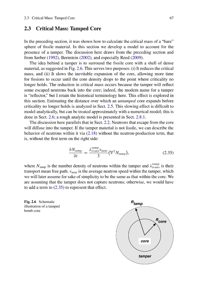
material, as suggested in Fig. 2.6. This serves two purposes: (i) It reduces the critical
mass, and (ii) It slows the inevitable expansion of the core, allowing more time
for fissions to occur until the core density drops to the point where criticality no
longer holds. The reduction in critical mass occurs because the tamper will reflect
some escaped neutrons back into the core; indeed, the modern name for a tamper
is “reflector,” but I retain the historical terminology here. This effect is explored in
this section. Estimating the distance over which an untamped core expands before
criticality no longer holds is analyzed in Sect. 2.5. This slowing effect is difficult to
model analytically, but can be treated approximately with a numerical model; this is
done in Sect. 2.6; a rough analytic model is presented in Sect. 2.8.1.
The discussion here parallels that in Sect. 2.2. Neutrons that escape from the core
will diffuse into the tamper. If the tamper material is not fissile, we can describe the
behavior of neutrons within it via (2.18) without the neutron-production term, that
is, without the first term on the right side:
∂ N tamp
∂t
=
λ
tamp
trans v neut
3
∇
2 N tamp
,
(2.35)
where N tamp is the number density of neutrons within the tamper and λ
tamp
trans is their
transport mean free path. v neut is the average neutron speed within the tamper, which
we will later assume for sake of simplicity to be the same as that within the core. We
are assuming that the tamper does not capture neutrons; otherwise, we would have
to add a term to (2.35) to represent that effect.
Fig. 2.6 Schematic
illustration of a tamped
bomb core
67
2.3 Critical Mass: Tamped Core
In the preceding section, it was shown how to calculate the critical mass of a “bare”
sphere of fissile material. In this section we develop a model to account for the
presence of a tamper. The discussion here draws from the preceding section and
from Serber (1992), Bernstein (2002), and especially Reed (2009).
The idea behind a tamper is to surround the fissile core with a shell of dense
material, as suggested in Fig. 2.6. This serves two purposes: (i) It reduces the critical
mass, and (ii) It slows the inevitable expansion of the core, allowing more time
for fissions to occur until the core density drops to the point where criticality no
longer holds. The reduction in critical mass occurs because the tamper will reflect
some escaped neutrons back into the core; indeed, the modern name for a tamper
is “reflector,” but I retain the historical terminology here. This effect is explored in
this section. Estimating the distance over which an untamped core expands before
criticality no longer holds is analyzed in Sect. 2.5. This slowing effect is difficult to
model analytically, but can be treated approximately with a numerical model; this is
done in Sect. 2.6; a rough analytic model is presented in Sect. 2.8.1.
The discussion here parallels that in Sect. 2.2. Neutrons that escape from the core
will diffuse into the tamper. If the tamper material is not fissile, we can describe the
behavior of neutrons within it via (2.18) without the neutron-production term, that
is, without the first term on the right side:
∂ N tamp
∂t
=
λ
tamp
trans v neut
3
∇
2 N tamp
,
(2.35)
where N tamp is the number density of neutrons within the tamper and λ
tamp
trans is their
transport mean free path. v neut is the average neutron speed within the tamper, which
we will later assume for sake of simplicity to be the same as that within the core. We
are assuming that the tamper does not capture neutrons; otherwise, we would have
to add a term to (2.35) to represent that effect.
Fig. 2.6 Schematic
illustration of a tamped
bomb core