

4 OPV with a Crystalline Organic Pigment Active Layer Up to 10 μm
8 3
-5
0
5
10
15
20
-2
-1.5
-1
-0.5
0
0.5
1
Current density (mA/cm 2
)
Voltage (V)
2
A4-2l2bp
C1-1l2bp
with all effects
without HTL/template
without co-evaporant
0
10
20
30
40
50
60
70
80
90
100
350 400 450 500 550 600 650 700 750 800 850 900
IPCE (%)
Wave length (nm)
with all effects
without HTL/template
without co-evaporant
(b)
(a)
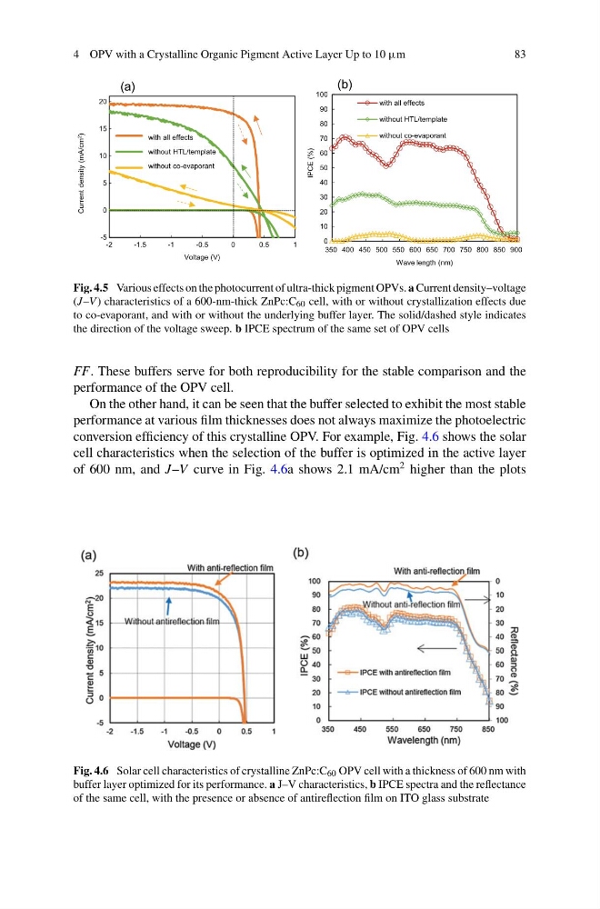
Fig. 4.5 Various effects on the photocurrent of ultra-thick pigment OPVs. a Current density–voltage
(J–V ) characteristics of a 600-nm-thick ZnPc:C 60 cell, with or without crystallization effects due
to co-evaporant, and with or without the underlying buffer layer. The solid/dashed style indicates
the direction of the voltage sweep. b IPCE spectrum of the same set of OPV cells
FF. These buffers serve for both reproducibility for the stable comparison and the
performance of the OPV cell.
On the other hand, it can be seen that the buffer selected to exhibit the most stable
performance at various film thicknesses does not always maximize the photoelectric
conversion efficiency of this crystalline OPV. For example, Fig. 4.6 shows the solar
cell characteristics when the selection of the buffer is optimized in the active layer
of 600 nm, and J–V curve in Fig. 4.6a shows 2.1 mA/cm
2 higher than the plots
Fig. 4.6 Solar cell characteristics of crystalline ZnPc:C 60 OPV cell with a thickness of 600 nm with
buffer layer optimized for its performance. a J–V characteristics, b IPCE spectra and the reflectance
of the same cell, with the presence or absence of antireflection film on ITO glass substrate
8 3
-5
0
5
10
15
20
-2
-1.5
-1
-0.5
0
0.5
1
Current density (mA/cm 2
)
Voltage (V)
2
A4-2l2bp
C1-1l2bp
with all effects
without HTL/template
without co-evaporant
0
10
20
30
40
50
60
70
80
90
100
350 400 450 500 550 600 650 700 750 800 850 900
IPCE (%)
Wave length (nm)
with all effects
without HTL/template
without co-evaporant
(b)
(a)
Fig. 4.5 Various effects on the photocurrent of ultra-thick pigment OPVs. a Current density–voltage
(J–V ) characteristics of a 600-nm-thick ZnPc:C 60 cell, with or without crystallization effects due
to co-evaporant, and with or without the underlying buffer layer. The solid/dashed style indicates
the direction of the voltage sweep. b IPCE spectrum of the same set of OPV cells
FF. These buffers serve for both reproducibility for the stable comparison and the
performance of the OPV cell.
On the other hand, it can be seen that the buffer selected to exhibit the most stable
performance at various film thicknesses does not always maximize the photoelectric
conversion efficiency of this crystalline OPV. For example, Fig. 4.6 shows the solar
cell characteristics when the selection of the buffer is optimized in the active layer
of 600 nm, and J–V curve in Fig. 4.6a shows 2.1 mA/cm
2 higher than the plots
Fig. 4.6 Solar cell characteristics of crystalline ZnPc:C 60 OPV cell with a thickness of 600 nm with
buffer layer optimized for its performance. a J–V characteristics, b IPCE spectra and the reflectance
of the same cell, with the presence or absence of antireflection film on ITO glass substrate