

9 Parts-Per-Million-Level Doping Effects …
231
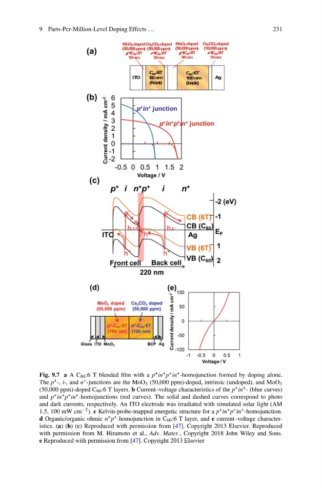
Fig. 9.7 a A C 60 :6 T blended film with a p + in + p + in + -homojunction formed by doping alone.
The p + -, i-, and n + -junctions are the MoO 3 (50,000 ppm)-doped, intrinsic (undoped), and MoO 3
(50,000 ppm)-doped C 60 :6 T layers. b Current–voltage characteristics of the p + in + - (blue curves)
and p + in + p + in + -homojunctions (red curves). The solid and dashed curves correspond to photo
and dark currents, respectively. An ITO electrode was irradiated with simulated solar light (AM
1.5, 100 mW cm −2 ). c Kelvin-probe-mapped energetic structure for a p + in + p + in + -homojunction.
d Organic/organic ohmic n + p + -homojunction in C 60 :6 T layer, and e current–voltage characteristics. (a) (b) (c) Reproduced with permission from [47]. Copyright 2013 Elsevier. Reproduced
with permission from M. Hiramoto et al., Adv. Mater., Copyright 2018 John Wiley and Sons.
e Reproduced with permission from [47]. Copyright 2013 Elsevier
231
Fig. 9.7 a A C 60 :6 T blended film with a p + in + p + in + -homojunction formed by doping alone.
The p + -, i-, and n + -junctions are the MoO 3 (50,000 ppm)-doped, intrinsic (undoped), and MoO 3
(50,000 ppm)-doped C 60 :6 T layers. b Current–voltage characteristics of the p + in + - (blue curves)
and p + in + p + in + -homojunctions (red curves). The solid and dashed curves correspond to photo
and dark currents, respectively. An ITO electrode was irradiated with simulated solar light (AM
1.5, 100 mW cm −2 ). c Kelvin-probe-mapped energetic structure for a p + in + p + in + -homojunction.
d Organic/organic ohmic n + p + -homojunction in C 60 :6 T layer, and e current–voltage characteristics. (a) (b) (c) Reproduced with permission from [47]. Copyright 2013 Elsevier. Reproduced
with permission from M. Hiramoto et al., Adv. Mater., Copyright 2018 John Wiley and Sons.
e Reproduced with permission from [47]. Copyright 2013 Elsevier