

212
S. Izawa
1.E-05
1.E-04
1.E-03
1.E-02
1.E-01
1.E+00
1
1.2
1.4
1.6
1.8
2
14
15
Energy (eV)
EQE
-8
-6
-4
-2
0
2
4
6
8
-1
-0.5
0
0.5
1
14
15
Current density (mA cm -2
)
Voltage (V)
(b)
(c)
(d)
(a)
RefPDI
4SubPDI
0
0.2
0.4
0.6
0.8
1
V CS
V R
V NR
4SubPDI
RefPDI
Voltage loss (V)
4SubPDI
RefPDI
4SubPDI
RefPDI
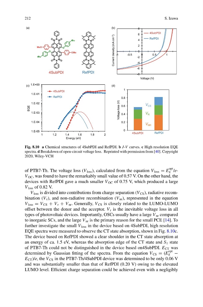
Fig. 8.10 a Chemical structures of 4SubPDI and RefPDI. b J-V curves. c High resolution EQE
spectra. d Breakdown of open-circuit voltage loss. Reprinted with permission from [40]. Copyright
2020, Wiley-VCH
of PTB7-Th. The voltage loss (V loss ), calculated from the equation V loss = E
opt
g /eV OC , was found to have the remarkably small value of 0.57 V. On the other hand, the
devices with RefPDI gave a much smaller V OC of 0.75 V, which produced a large
V loss of 0.82 V.
V loss is divided into contributions from charge separation (V CS ), radiative recombination (V r ), and non-radiative recombination (V nr ), represented in the equation
V loss = V CS + V r + V nr . Generally, V CS is closely related to the LUMO-LUMO
offset between the donor and the acceptor. V r is the inevitable voltage loss in all
types of photovoltaic devices. Importantly, OSCs usually have a large V nr compared
to inorganic SCs, and the large V nr is the primary reason for the small PCE [14]. To
further investigate the small V loss in the device based on 4SubPDI, high resolution
EQE spectra were measured to observe the CT state absorption, shown in Fig. 8.10c.
The device based on RefPDI showed a clear shoulder in the CT state absorption at
an energy of ca. 1.5 eV, whereas the absorption edge of the CT state and S 1 state
of PTB7-Th could not be distinguished in the device based on4SubPDI. E CT was
determined by Gaussian fitting of the spectra. From the equation V CS = (E
opt
g −
E CT )/e, the V CS in the PTB7-Th/4SubPDI device was determined to be only 0.06 V
and was substantially smaller than that of RefPDI (0.20 V) owing to the elevated
LUMO level. Efficient charge separation could be achieved even with a negligibly
S. Izawa
1.E-05
1.E-04
1.E-03
1.E-02
1.E-01
1.E+00
1
1.2
1.4
1.6
1.8
2
14
15
Energy (eV)
EQE
-8
-6
-4
-2
0
2
4
6
8
-1
-0.5
0
0.5
1
14
15
Current density (mA cm -2
)
Voltage (V)
(b)
(c)
(d)
(a)
RefPDI
4SubPDI
0
0.2
0.4
0.6
0.8
1
V CS
V R
V NR
4SubPDI
RefPDI
Voltage loss (V)
4SubPDI
RefPDI
4SubPDI
RefPDI
Fig. 8.10 a Chemical structures of 4SubPDI and RefPDI. b J-V curves. c High resolution EQE
spectra. d Breakdown of open-circuit voltage loss. Reprinted with permission from [40]. Copyright
2020, Wiley-VCH
of PTB7-Th. The voltage loss (V loss ), calculated from the equation V loss = E
opt
g /eV OC , was found to have the remarkably small value of 0.57 V. On the other hand, the
devices with RefPDI gave a much smaller V OC of 0.75 V, which produced a large
V loss of 0.82 V.
V loss is divided into contributions from charge separation (V CS ), radiative recombination (V r ), and non-radiative recombination (V nr ), represented in the equation
V loss = V CS + V r + V nr . Generally, V CS is closely related to the LUMO-LUMO
offset between the donor and the acceptor. V r is the inevitable voltage loss in all
types of photovoltaic devices. Importantly, OSCs usually have a large V nr compared
to inorganic SCs, and the large V nr is the primary reason for the small PCE [14]. To
further investigate the small V loss in the device based on 4SubPDI, high resolution
EQE spectra were measured to observe the CT state absorption, shown in Fig. 8.10c.
The device based on RefPDI showed a clear shoulder in the CT state absorption at
an energy of ca. 1.5 eV, whereas the absorption edge of the CT state and S 1 state
of PTB7-Th could not be distinguished in the device based on4SubPDI. E CT was
determined by Gaussian fitting of the spectra. From the equation V CS = (E
opt
g −
E CT )/e, the V CS in the PTB7-Th/4SubPDI device was determined to be only 0.06 V
and was substantially smaller than that of RefPDI (0.20 V) owing to the elevated
LUMO level. Efficient charge separation could be achieved even with a negligibly