

3 Reactor Kinetics
63
1/8
p15EUEU) shown in Fig. 2A.13 is composed of a total of 60 unit cells: 30
unit cells with HEU plate 1/8
thick and Pb–Bi plate 3.426 mm thick, and 30 unit
cells with HEU plate 1/8
thick and a polyethylene plate 1/8
thick. As shown in
Fig. 2A.14, numeral 16
(3/8
p16EU) corresponds to the number of fuel plates in
the partial fuel assembly used for reaching critical mass. The neutron spectra were
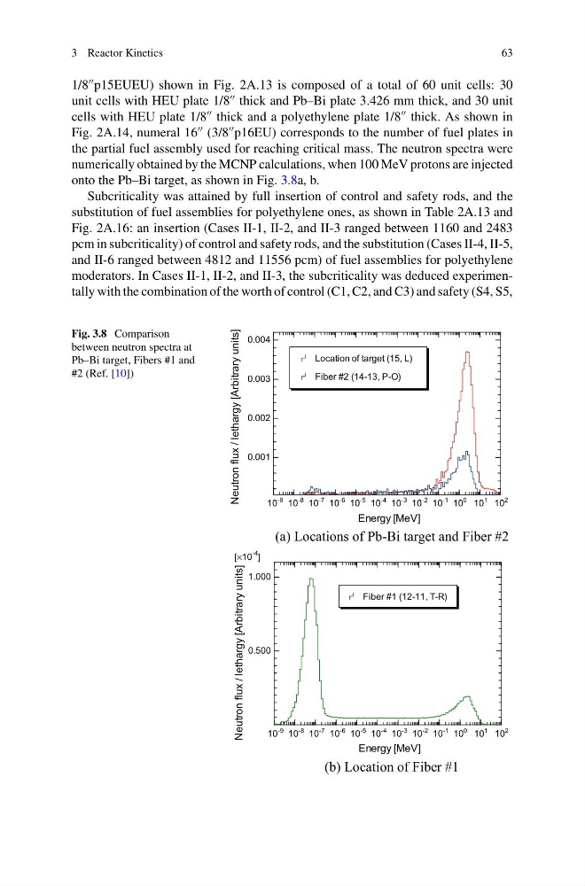
numerically obtained by the MCNP calculations, when 100 MeV protons are injected
onto the Pb–Bi target, as shown in Fig. 3.8a, b.
Subcriticality was attained by full insertion of control and safety rods, and the
substitution of fuel assemblies for polyethylene ones, as shown in Table 2A.13 and
Fig. 2A.16: an insertion (Cases II-1, II-2, and II-3 ranged between 1160 and 2483
pcm in subcriticality) of control and safety rods, and the substitution (Cases II-4, II-5,
and II-6 ranged between 4812 and 11556 pcm) of fuel assemblies for polyethylene
moderators. In Cases II-1, II-2, and II-3, the subcriticality was deduced experimentally with the combination of the worth of control (C1, C2, and C3) and safety (S4, S5,
Fig. 3.8 Comparison
between neutron spectra at
Pb–Bi target, Fibers #1 and
#2 (Ref. [10])
(a) Locations of Pb-Bi target and Fiber #2
(b) Location of Fiber #1
10
-9 10
-8 10
-7 10
-6 10
-5 10
-4 10
-3 10
-2 10
-1 10
0 10
1 10
2
0.500
1.000
[×10
-4
]
Neutron flux / lethargy [Arbitrary units]
Energy [MeV]
Fiber #1 (12-11, T-R)
10
-9 10
-8 10
-7 10
-6 10
-5 10
-4 10
-3 10
-2 10
-1 10
0 10
1 10
2
0.001
0.002
0.003
0.004
Energy [MeV]
Location of target (15, L)
Fiber #2 (14-13, P-O)
Neutron flux / lethargy [Arbitrary units]
63
1/8
p15EUEU) shown in Fig. 2A.13 is composed of a total of 60 unit cells: 30
unit cells with HEU plate 1/8
thick and Pb–Bi plate 3.426 mm thick, and 30 unit
cells with HEU plate 1/8
thick and a polyethylene plate 1/8
thick. As shown in
Fig. 2A.14, numeral 16
(3/8
p16EU) corresponds to the number of fuel plates in
the partial fuel assembly used for reaching critical mass. The neutron spectra were
numerically obtained by the MCNP calculations, when 100 MeV protons are injected
onto the Pb–Bi target, as shown in Fig. 3.8a, b.
Subcriticality was attained by full insertion of control and safety rods, and the
substitution of fuel assemblies for polyethylene ones, as shown in Table 2A.13 and
Fig. 2A.16: an insertion (Cases II-1, II-2, and II-3 ranged between 1160 and 2483
pcm in subcriticality) of control and safety rods, and the substitution (Cases II-4, II-5,
and II-6 ranged between 4812 and 11556 pcm) of fuel assemblies for polyethylene
moderators. In Cases II-1, II-2, and II-3, the subcriticality was deduced experimentally with the combination of the worth of control (C1, C2, and C3) and safety (S4, S5,
Fig. 3.8 Comparison
between neutron spectra at
Pb–Bi target, Fibers #1 and
#2 (Ref. [10])
(a) Locations of Pb-Bi target and Fiber #2
(b) Location of Fiber #1
10
-9 10
-8 10
-7 10
-6 10
-5 10
-4 10
-3 10
-2 10
-1 10
0 10
1 10
2
0.500
1.000
[×10
-4
]
Neutron flux / lethargy [Arbitrary units]
Energy [MeV]
Fiber #1 (12-11, T-R)
10
-9 10
-8 10
-7 10
-6 10
-5 10
-4 10
-3 10
-2 10
-1 10
0 10
1 10
2
0.001
0.002
0.003
0.004
Energy [MeV]
Location of target (15, L)
Fiber #2 (14-13, P-O)
Neutron flux / lethargy [Arbitrary units]