

56
C. H. Pyeon
depending on the subcriticality and the requisite measurements. The duty ratio was
limited to 1% as a design limit.
3.1.1.2 Kinetics Parameters
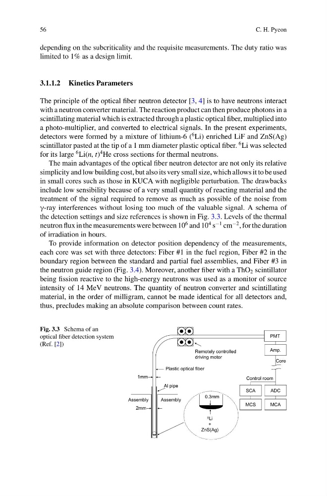
The principle of the optical fiber neutron detector [3, 4] is to have neutrons interact
with a neutron converter material. The reaction product can then produce photons in a
scintillating material which is extracted through a plastic optical fiber, multiplied into
a photo-multiplier, and converted to electrical signals. In the present experiments,
detectors were formed by a mixture of lithium-6 (
6 Li) enriched LiF and ZnS(Ag)
scintillator pasted at the tip of a 1 mm diameter plastic optical fiber.
6 Li was selected
for its large
6 Li(n, t)
4 He cross sections for thermal neutrons.
The main advantages of the optical fiber neutron detector are not only its relative
simplicity and low building cost, but also its very small size, which allows it to be used
in small cores such as those in KUCA with negligible perturbation. The drawbacks
include low sensibility because of a very small quantity of reacting material and the
treatment of the signal required to remove as much as possible of the noise from
γ-ray interferences without losing too much of the valuable signal. A schema of
the detection settings and size references is shown in Fig. 3.3. Levels of the thermal
neutron flux in the measurements were between 10
6 and 10
4 s
−1 cm
−2 , for the duration
of irradiation in hours.
To provide information on detector position dependency of the measurements,
each core was set with three detectors: Fiber #1 in the fuel region, Fiber #2 in the
boundary region between the standard and partial fuel assemblies, and Fiber #3 in
the neutron guide region (Fig. 3.4). Moreover, another fiber with a ThO 2 scintillator
being fission reactive to the high-energy neutrons was used as a monitor of source
intensity of 14 MeV neutrons. The quantity of neutron converter and scintillating
material, in the order of milligram, cannot be made identical for all detectors and,
thus, precludes making an absolute comparison between count rates.
Fig. 3.3 Schema of an
optical fiber detection system
(Ref. [2])
2mm
1mm
Assembly
Assembly
Al pipe
Remotely controlled
driving motor
0.3mm
PMT
Amp.
SCA
ADC
MCA
MCS
Core
Control room
6 Li
+
ZnS(Ag)
Plastic optical fiber
C. H. Pyeon
depending on the subcriticality and the requisite measurements. The duty ratio was
limited to 1% as a design limit.
3.1.1.2 Kinetics Parameters
The principle of the optical fiber neutron detector [3, 4] is to have neutrons interact
with a neutron converter material. The reaction product can then produce photons in a
scintillating material which is extracted through a plastic optical fiber, multiplied into
a photo-multiplier, and converted to electrical signals. In the present experiments,
detectors were formed by a mixture of lithium-6 (
6 Li) enriched LiF and ZnS(Ag)
scintillator pasted at the tip of a 1 mm diameter plastic optical fiber.
6 Li was selected
for its large
6 Li(n, t)
4 He cross sections for thermal neutrons.
The main advantages of the optical fiber neutron detector are not only its relative
simplicity and low building cost, but also its very small size, which allows it to be used
in small cores such as those in KUCA with negligible perturbation. The drawbacks
include low sensibility because of a very small quantity of reacting material and the
treatment of the signal required to remove as much as possible of the noise from
γ-ray interferences without losing too much of the valuable signal. A schema of
the detection settings and size references is shown in Fig. 3.3. Levels of the thermal
neutron flux in the measurements were between 10
6 and 10
4 s
−1 cm
−2 , for the duration
of irradiation in hours.
To provide information on detector position dependency of the measurements,
each core was set with three detectors: Fiber #1 in the fuel region, Fiber #2 in the
boundary region between the standard and partial fuel assemblies, and Fiber #3 in
the neutron guide region (Fig. 3.4). Moreover, another fiber with a ThO 2 scintillator
being fission reactive to the high-energy neutrons was used as a monitor of source
intensity of 14 MeV neutrons. The quantity of neutron converter and scintillating
material, in the order of milligram, cannot be made identical for all detectors and,
thus, precludes making an absolute comparison between count rates.
Fig. 3.3 Schema of an
optical fiber detection system
(Ref. [2])
2mm
1mm
Assembly
Assembly
Al pipe
Remotely controlled
driving motor
0.3mm
PMT
Amp.
SCA
ADC
MCA
MCS
Core
Control room
6 Li
+
ZnS(Ag)
Plastic optical fiber