

264
Appendix A2: 235 U-Fueled and Pb–Bi–Zoned ADS Core
A2.1.2.2 PNS and Feynman-α Methods
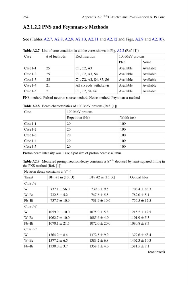
See (Tables A2.7, A2.8, A2.9, A2.10, A2.11 and A2.12 and Figs. A2.9 and A2.10).
Table A2.7 List of core condition in all the cores shown in Fig. A2.2 (Ref. [1])
Case
# of fuel rods
Rod insertion
100 MeV protons
PNS
Noise
Case I-1
25
C1, C2, A3
Available
Available
Case I-2
25
C1, C2, A3, S4
Available
Available
Case I-3
25
C1, C2, A3, S4, S5, S6
Available
Available
Case I-4
21
All six rods withdrawn
Available
Available
Case I-5
21
C1, C2, S4, S6
Available
Available
PNS method: Pulsed-neutron source method; Noise method: Feynman-α method
Table A2.8 Beam characteristics of 100 MeV protons (Ref. [1])
Case
100 MeV protons
Repetition (Hz)
Width (ns)
Case I-1
20
100
Case I-2
20
100
Case I-3
20
100
Case I-4
20
100
Case I-5
20
100
Proton beam intensity was 1 nA; Spot size of proton beams: 40 mm.
Table A2.9 Measured prompt neutron decay constants α [s −1 ] deduced by least-squared fitting in
the PNS method (Ref. [1])
Neutron decay constants α [s −1 ]
Target
BF 3 #1 in (10, U)
BF 3 #2 in (15, X)
Optical fiber
Case I-1
W
737.1 ± 56.0
739.6 ± 9.5
706.4 ± 83.3
W–Be
732.5 ± 5.2
747.8 ± 5.5
782.0 ± 5.1
Pb–Bi
737.7 ± 10.9
731.9 ± 10.6
756.5 ± 12.5
Case I-2
W
1059.9 ± 10.0
1075.0 ± 5.8
1215.2 ± 12.5
W–Be
1062.7 ± 10.0
1085.6 ± 4.0
1101.9 ± 5.3
Pb–Bi
1070.1 ± 21.5
1072.0 ± 20.0
1080.8 ± 8.3
Case I-3
W
1364.2 ± 8.4
1372.5 ± 9.9
1379.6 ± 68.4
W–Be
1377.2 ± 6.5
1383.2 ± 6.8
1402.3 ± 10.3
Pb–Bi
1338.0 ± 3.7
1358.3 ± 4.0
1381.5 ± 7.1
(continued)
Appendix A2: 235 U-Fueled and Pb–Bi–Zoned ADS Core
A2.1.2.2 PNS and Feynman-α Methods
See (Tables A2.7, A2.8, A2.9, A2.10, A2.11 and A2.12 and Figs. A2.9 and A2.10).
Table A2.7 List of core condition in all the cores shown in Fig. A2.2 (Ref. [1])
Case
# of fuel rods
Rod insertion
100 MeV protons
PNS
Noise
Case I-1
25
C1, C2, A3
Available
Available
Case I-2
25
C1, C2, A3, S4
Available
Available
Case I-3
25
C1, C2, A3, S4, S5, S6
Available
Available
Case I-4
21
All six rods withdrawn
Available
Available
Case I-5
21
C1, C2, S4, S6
Available
Available
PNS method: Pulsed-neutron source method; Noise method: Feynman-α method
Table A2.8 Beam characteristics of 100 MeV protons (Ref. [1])
Case
100 MeV protons
Repetition (Hz)
Width (ns)
Case I-1
20
100
Case I-2
20
100
Case I-3
20
100
Case I-4
20
100
Case I-5
20
100
Proton beam intensity was 1 nA; Spot size of proton beams: 40 mm.
Table A2.9 Measured prompt neutron decay constants α [s −1 ] deduced by least-squared fitting in
the PNS method (Ref. [1])
Neutron decay constants α [s −1 ]
Target
BF 3 #1 in (10, U)
BF 3 #2 in (15, X)
Optical fiber
Case I-1
W
737.1 ± 56.0
739.6 ± 9.5
706.4 ± 83.3
W–Be
732.5 ± 5.2
747.8 ± 5.5
782.0 ± 5.1
Pb–Bi
737.7 ± 10.9
731.9 ± 10.6
756.5 ± 12.5
Case I-2
W
1059.9 ± 10.0
1075.0 ± 5.8
1215.2 ± 12.5
W–Be
1062.7 ± 10.0
1085.6 ± 4.0
1101.9 ± 5.3
Pb–Bi
1070.1 ± 21.5
1072.0 ± 20.0
1080.8 ± 8.3
Case I-3
W
1364.2 ± 8.4
1372.5 ± 9.9
1379.6 ± 68.4
W–Be
1377.2 ± 6.5
1383.2 ± 6.8
1402.3 ± 10.3
Pb–Bi
1338.0 ± 3.7
1358.3 ± 4.0
1381.5 ± 7.1
(continued)