

the Te-Chrom and Te-Shuttle modules for the dispensing into the
RoboColumns. Custom liquid classes are employed only for the
sanitization of the stainless-steel tips and during the implementation of the robot’s liquid detect function (see Notes 6–8).
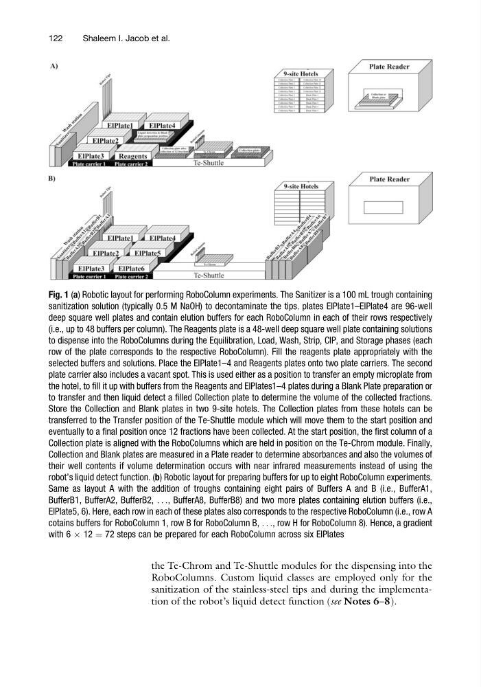
Fig. 1 (a) Robotic layout for performing RoboColumn experiments. The Sanitizer is a 100 mL trough containing
sanitization solution (typically 0.5 M NaOH) to decontaminate the tips. plates ElPlate1–ElPlate4 are 96-well
deep square well plates and contain elution buffers for each RoboColumn in each of their rows respectively
(i.e., up to 48 buffers per column). The Reagents plate is a 48-well deep square well plate containing solutions
to dispense into the RoboColumns during the Equilibration, Load, Wash, Strip, CIP, and Storage phases (each
row of the plate corresponds to the respective RoboColumn). Fill the reagents plate appropriately with the
selected buffers and solutions. Place the ElPlate1–4 and Reagents plates onto two plate carriers. The second
plate carrier also includes a vacant spot. This is used either as a position to transfer an empty microplate from
the hotel, to fill it up with buffers from the Reagents and ElPlates1–4 plates during a Blank Plate preparation or
to transfer and then liquid detect a filled Collection plate to determine the volume of the collected fractions.
Store the Collection and Blank plates in two 9-site hotels. The Collection plates from these hotels can be
transferred to the Transfer position of the Te-Shuttle module which will move them to the start position and
eventually to a final position once 12 fractions have been collected. At the start position, the first column of a
Collection plate is aligned with the RoboColumns which are held in position on the Te-Chrom module. Finally,
Collection and Blank plates are measured in a Plate reader to determine absorbances and also the volumes of
their well contents if volume determination occurs with near infrared measurements instead of using the
robot’s liquid detect function. (b) Robotic layout for preparing buffers for up to eight RoboColumn experiments.
Same as layout A with the addition of troughs containing eight pairs of Buffers A and B (i.e., BufferA1,
BufferB1, BufferA2, BufferB2, . . ., BufferA8, BufferB8) and two more plates containing elution buffers (i.e.,
ElPlate5, 6). Here, each row in each of these plates also corresponds to the respective RoboColumn (i.e., row A
cotains buffers for RoboColumn 1, row B for RoboColumn B, . . ., row H for RoboColumn 8). Hence, a gradient
with 6 Â 12 ¼ 72 steps can be prepared for each RoboColumn across six ElPlates
122
Shaleem I. Jacob et al.
RoboColumns. Custom liquid classes are employed only for the
sanitization of the stainless-steel tips and during the implementation of the robot’s liquid detect function (see Notes 6–8).
Fig. 1 (a) Robotic layout for performing RoboColumn experiments. The Sanitizer is a 100 mL trough containing
sanitization solution (typically 0.5 M NaOH) to decontaminate the tips. plates ElPlate1–ElPlate4 are 96-well
deep square well plates and contain elution buffers for each RoboColumn in each of their rows respectively
(i.e., up to 48 buffers per column). The Reagents plate is a 48-well deep square well plate containing solutions
to dispense into the RoboColumns during the Equilibration, Load, Wash, Strip, CIP, and Storage phases (each
row of the plate corresponds to the respective RoboColumn). Fill the reagents plate appropriately with the
selected buffers and solutions. Place the ElPlate1–4 and Reagents plates onto two plate carriers. The second
plate carrier also includes a vacant spot. This is used either as a position to transfer an empty microplate from
the hotel, to fill it up with buffers from the Reagents and ElPlates1–4 plates during a Blank Plate preparation or
to transfer and then liquid detect a filled Collection plate to determine the volume of the collected fractions.
Store the Collection and Blank plates in two 9-site hotels. The Collection plates from these hotels can be
transferred to the Transfer position of the Te-Shuttle module which will move them to the start position and
eventually to a final position once 12 fractions have been collected. At the start position, the first column of a
Collection plate is aligned with the RoboColumns which are held in position on the Te-Chrom module. Finally,
Collection and Blank plates are measured in a Plate reader to determine absorbances and also the volumes of
their well contents if volume determination occurs with near infrared measurements instead of using the
robot’s liquid detect function. (b) Robotic layout for preparing buffers for up to eight RoboColumn experiments.
Same as layout A with the addition of troughs containing eight pairs of Buffers A and B (i.e., BufferA1,
BufferB1, BufferA2, BufferB2, . . ., BufferA8, BufferB8) and two more plates containing elution buffers (i.e.,
ElPlate5, 6). Here, each row in each of these plates also corresponds to the respective RoboColumn (i.e., row A
cotains buffers for RoboColumn 1, row B for RoboColumn B, . . ., row H for RoboColumn 8). Hence, a gradient
with 6 Â 12 ¼ 72 steps can be prepared for each RoboColumn across six ElPlates
122
Shaleem I. Jacob et al.