

2.6 Graded-Index (GI) Fibers
71
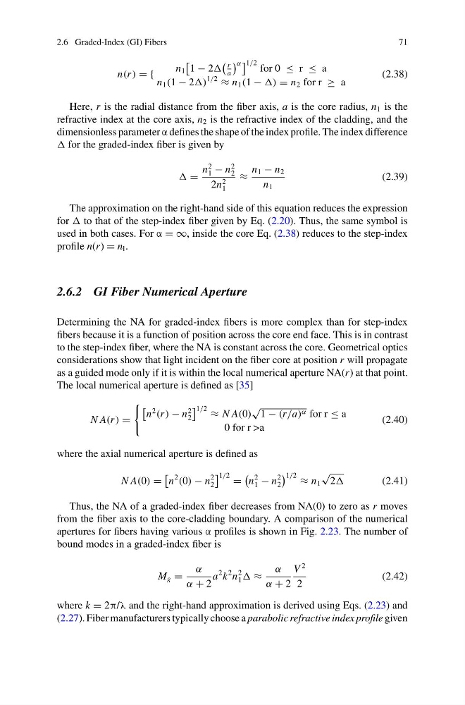
n(r ) = {
n 1
1 − 2
r
a
α 1/2 for 0 ≤ r ≤ a
n 1 (1 − 2)
1/2
≈ n 1 (1 − ) = n 2 for r ≥ a
(2.38)
Here, r is the radial distance from the fiber axis, a is the core radius, n 1 is the
refractive index at the core axis, n 2 is the refractive index of the cladding, and the
dimensionless parameter α defines the shape of the index profile. The index difference
for the graded-index fiber is given by
=
n
2
1 − n
2
2
2n
2
1
≈
n 1 − n 2
n 1
(2.39)
The approximation on the right-hand side of this equation reduces the expression
for to that of the step-index fiber given by Eq. (2.20). Thus, the same symbol is
used in both cases. For α = ∞, inside the core Eq. (2.38) reduces to the step-index
profile n(r) = n l .
2.6.2 GI Fiber Numerical Aperture
Determining the NA for graded-index fibers is more complex than for step-index
fibers because it is a function of position across the core end face. This is in contrast
to the step-index fiber, where the NA is constant across the core. Geometrical optics
considerations show that light incident on the fiber core at position r will propagate
as a guided mode only if it is within the local numerical aperture NA(r) at that point.
The local numerical aperture is defined as [35]
N A(r ) =
n
2
(r ) − n
2
2
1/2 ≈ N A(0)
√
1 − (r/a) α for r ≤ a
0 for r >a
(2.40)
where the axial numerical aperture is defined as
N A(0) =
n
2
(0) − n
2
2
1/2 =
n
2
1 − n
2
2
1/2 ≈ n 1
√
2
(2.41)
Thus, the NA of a graded-index fiber decreases from NA(0) to zero as r moves
from the fiber axis to the core-cladding boundary. A comparison of the numerical
apertures for fibers having various α profiles is shown in Fig. 2.23. The number of
bound modes in a graded-index fiber is
M g =
α
α + 2
a
2 k
2 n
2
1 ≈
α
α + 2
V
2
2
(2.42)
where k = 2π/λ and the right-hand approximation is derived using Eqs. (2.23) and
(2.27). Fiber manufacturers typically choose a parabolic refractive index profile given
71
n(r ) = {
n 1
1 − 2
r
a
α 1/2 for 0 ≤ r ≤ a
n 1 (1 − 2)
1/2
≈ n 1 (1 − ) = n 2 for r ≥ a
(2.38)
Here, r is the radial distance from the fiber axis, a is the core radius, n 1 is the
refractive index at the core axis, n 2 is the refractive index of the cladding, and the
dimensionless parameter α defines the shape of the index profile. The index difference
for the graded-index fiber is given by
=
n
2
1 − n
2
2
2n
2
1
≈
n 1 − n 2
n 1
(2.39)
The approximation on the right-hand side of this equation reduces the expression
for to that of the step-index fiber given by Eq. (2.20). Thus, the same symbol is
used in both cases. For α = ∞, inside the core Eq. (2.38) reduces to the step-index
profile n(r) = n l .
2.6.2 GI Fiber Numerical Aperture
Determining the NA for graded-index fibers is more complex than for step-index
fibers because it is a function of position across the core end face. This is in contrast
to the step-index fiber, where the NA is constant across the core. Geometrical optics
considerations show that light incident on the fiber core at position r will propagate
as a guided mode only if it is within the local numerical aperture NA(r) at that point.
The local numerical aperture is defined as [35]
N A(r ) =
n
2
(r ) − n
2
2
1/2 ≈ N A(0)
√
1 − (r/a) α for r ≤ a
0 for r >a
(2.40)
where the axial numerical aperture is defined as
N A(0) =
n
2
(0) − n
2
2
1/2 =
n
2
1 − n
2
2
1/2 ≈ n 1
√
2
(2.41)
Thus, the NA of a graded-index fiber decreases from NA(0) to zero as r moves
from the fiber axis to the core-cladding boundary. A comparison of the numerical
apertures for fibers having various α profiles is shown in Fig. 2.23. The number of
bound modes in a graded-index fiber is
M g =
α
α + 2
a
2 k
2 n
2
1 ≈
α
α + 2
V
2
2
(2.42)
where k = 2π/λ and the right-hand approximation is derived using Eqs. (2.23) and
(2.27). Fiber manufacturers typically choose a parabolic refractive index profile given