

54
2 Optical Fiber Structures and Light Guiding Principles
n 2 Cladding
n 2 Cladding
n 1 Core
Refracted ray
Reflected ray
Acceptance
cone
Entrance rays
θ 0
φ
θ
n < n 1
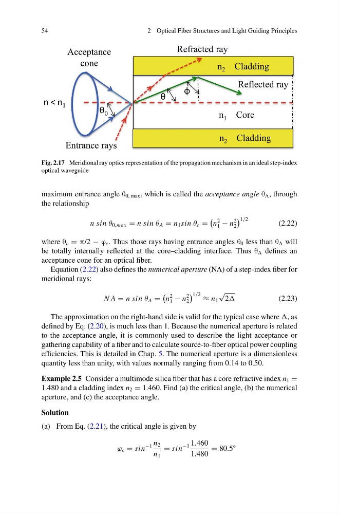
Fig. 2.17 Meridional ray optics representation of the propagation mechanism in an ideal step-index
optical waveguide
maximum entrance angle θ 0, max , which is called the acceptance angle θ A , through
the relationship
n sin θ 0,max = n sin θ A = n 1 sin θ c =
n
2
1 − n
2
2
1/2
(2.22)
where θ c = π/2 − ϕ c . Thus those rays having entrance angles θ 0 less than θ A will
be totally internally reflected at the core–cladding interface. Thus θ A defines an
acceptance cone for an optical fiber.
Equation (2.22) also defines the numerical aperture (NA) of a step-index fiber for
meridional rays:
N A = n sin θ A =
n
2
1 − n
2
2
1/2 ≈ n 1
√
2
(2.23)
The approximation on the right-hand side is valid for the typical case where , as
defined by Eq. (2.20), is much less than 1. Because the numerical aperture is related
to the acceptance angle, it is commonly used to describe the light acceptance or
gathering capability of a fiber and to calculate source-to-fiber optical power coupling
efficiencies. This is detailed in Chap. 5. The numerical aperture is a dimensionless
quantity less than unity, with values normally ranging from 0.14 to 0.50.
Example 2.5 Consider a multimode silica fiber that has a core refractive index n 1 =
1.480 and a cladding index n 2 = 1.460. Find (a) the critical angle, (b) the numerical
aperture, and (c) the acceptance angle.
Solution
(a) From Eq. (2.21), the critical angle is given by
ϕ c = sin
−1 n 2
n 1
= sin
−1 1.460
1.480
= 80.5
◦
2 Optical Fiber Structures and Light Guiding Principles
n 2 Cladding
n 2 Cladding
n 1 Core
Refracted ray
Reflected ray
Acceptance
cone
Entrance rays
θ 0
φ
θ
n < n 1
Fig. 2.17 Meridional ray optics representation of the propagation mechanism in an ideal step-index
optical waveguide
maximum entrance angle θ 0, max , which is called the acceptance angle θ A , through
the relationship
n sin θ 0,max = n sin θ A = n 1 sin θ c =
n
2
1 − n
2
2
1/2
(2.22)
where θ c = π/2 − ϕ c . Thus those rays having entrance angles θ 0 less than θ A will
be totally internally reflected at the core–cladding interface. Thus θ A defines an
acceptance cone for an optical fiber.
Equation (2.22) also defines the numerical aperture (NA) of a step-index fiber for
meridional rays:
N A = n sin θ A =
n
2
1 − n
2
2
1/2 ≈ n 1
√
2
(2.23)
The approximation on the right-hand side is valid for the typical case where , as
defined by Eq. (2.20), is much less than 1. Because the numerical aperture is related
to the acceptance angle, it is commonly used to describe the light acceptance or
gathering capability of a fiber and to calculate source-to-fiber optical power coupling
efficiencies. This is detailed in Chap. 5. The numerical aperture is a dimensionless
quantity less than unity, with values normally ranging from 0.14 to 0.50.
Example 2.5 Consider a multimode silica fiber that has a core refractive index n 1 =
1.480 and a cladding index n 2 = 1.460. Find (a) the critical angle, (b) the numerical
aperture, and (c) the acceptance angle.
Solution
(a) From Eq. (2.21), the critical angle is given by
ϕ c = sin
−1 n 2
n 1
= sin
−1 1.460
1.480
= 80.5
◦