

14.4 Characterization of Optical Fibers
591
center of the core, as Fig. 14.5a shows. In this case, the attenuation contribution
arising from higher-order mode power loss is negligible. In Fig. 14.5b the spot size
is larger than the fiber core and the spot NA is larger than that of the fiber. For this
overfilled condition, those parts of the incident light beam that fall outside the fiber
core and outside the fiber NA are lost. In addition, there is a large contribution to the
attenuation arising from higher-mode power loss (see Sects. 5.1 and 5.3).
Steady-state equilibrium-mode distributions are typically achieved by the
mandrel-wrap method. In this procedure, excess higher-order cladding modes that
are launched by initially overexciting the fiber are filtered out by wrapping several
turns of fiber around a mandrel, which is about 1.0–1.5 cm in diameter. In singlemode fibers, this type of mode filter or mode stripper is used to eliminate cladding
modes from the fiber.
Insertion-Loss Method
For cables with connectors, one cannot use the cutback method. In this case, one
commonly uses an insertion-loss technique [9]. This is less accurate than the cutback
method but is intended for field measurements to give the total attenuation of a cable
assembly in decibels.
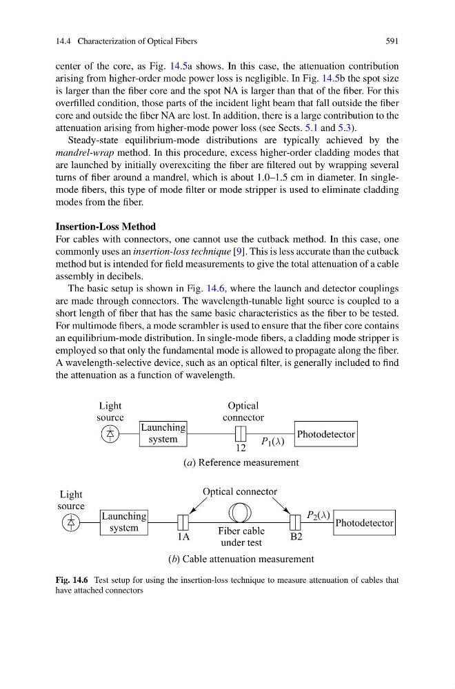
The basic setup is shown in Fig. 14.6, where the launch and detector couplings
are made through connectors. The wavelength-tunable light source is coupled to a
short length of fiber that has the same basic characteristics as the fiber to be tested.
For multimode fibers, a mode scrambler is used to ensure that the fiber core contains
an equilibrium-mode distribution. In single-mode fibers, a cladding mode stripper is
employed so that only the fundamental mode is allowed to propagate along the fiber.
A wavelength-selective device, such as an optical filter, is generally included to find
the attenuation as a function of wavelength.
Fig. 14.6 Test setup for using the insertion-loss technique to measure attenuation of cables that
have attached connectors