

536
13 Fiber Optic Communication Networks
occur less frequently than in a metro network where there tends to be a high turnover
rate in service requests and in wavelengths being transported. In addition, compared
to a metro network the wavelength spacing usually is much narrower in a long-haul
network and the optical amplifiers used must cover a wider spectral band. Section 13.7
has some examples of this topic.
13.5.1 Configurations of OADM Equipment
A number of different OADM configurations are possible. Most OADMs are
constructed using the WDM elements described in Chap. 10. These can be a series
of dielectric thin-film filters, an arrayed waveguide grating, a set of liquid crystal
devices, or a series of fiber Bragg gratings used in conjunction with optical circulators. The architecture selected for a particular application depends on implementation
factors such as the number of wavelengths to be dropped and added at a node, the
desired modularity of the OADM (e.g., how easy is it to upgrade this device), and
the constraint of whether random individual wavelengths or a neighboring group
of wavelengths should be processed. Here it will be assumed that N wavelengths
traveling on a single fiber enter the OADM and a subset M of them is processed at
the node. After processing, these M wavelengths can be reinserted onto the fiber line
to rejoin the through-going N − M channels.
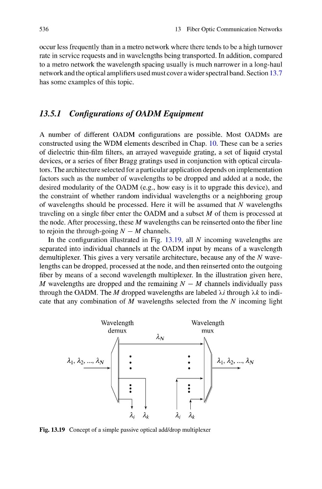
In the configuration illustrated in Fig. 13.19, all N incoming wavelengths are
separated into individual channels at the OADM input by means of a wavelength
demultiplexer. This gives a very versatile architecture, because any of the N wavelengths can be dropped, processed at the node, and then reinserted onto the outgoing
fiber by means of a second wavelength multiplexer. In the illustration given here,
M wavelengths are dropped and the remaining N − M channels individually pass
through the OADM. The M dropped wavelengths are labeled λi through λk to indicate that any combination of M wavelengths selected from the N incoming light
Fig. 13.19 Concept of a simple passive optical add/drop multiplexer