

418
10 Wavelength Division Multiplexing (WDM)
(c) Next at circulator C 3 the incoming wavelength λ 3 enters port 3 of circulator C 3 ,
exits from port 1, and then travels toward FBG 3 . After being reflected from FBG 3
it enters port 1 of circulator C 3 and exits from port 2 together with wavelengths
λ 1 and λ 2 .
(d) After a similar process takes place at circulator C 4 and filter FBG 4 to insert
wavelength λ 4 , the four wavelengths all exit together from port 2 of circulator
C 4 and can be coupled easily into a fiber.
The coupler size limitation when using FBGs is that one filter is needed for
each wavelength and normally the operation is sequential with wavelengths being
transmitted by one filter after another. Therefore the losses are not uniform from
channel to channel, because each wavelength goes through a different number of
circulators and fiber gratings, each of which adds loss to that channel. This may be
acceptable for a small number of channels, but the loss differential between the first
and last inserted wavelengths is a restriction for large channel counts.
10.5 Dielectric Thin-Film Filter (TFF)
A dielectric thin-film filter (TFF) is used as an optical bandpass filter [19–21]. This
means that it allows a particular very narrow wavelength band to pass straight through
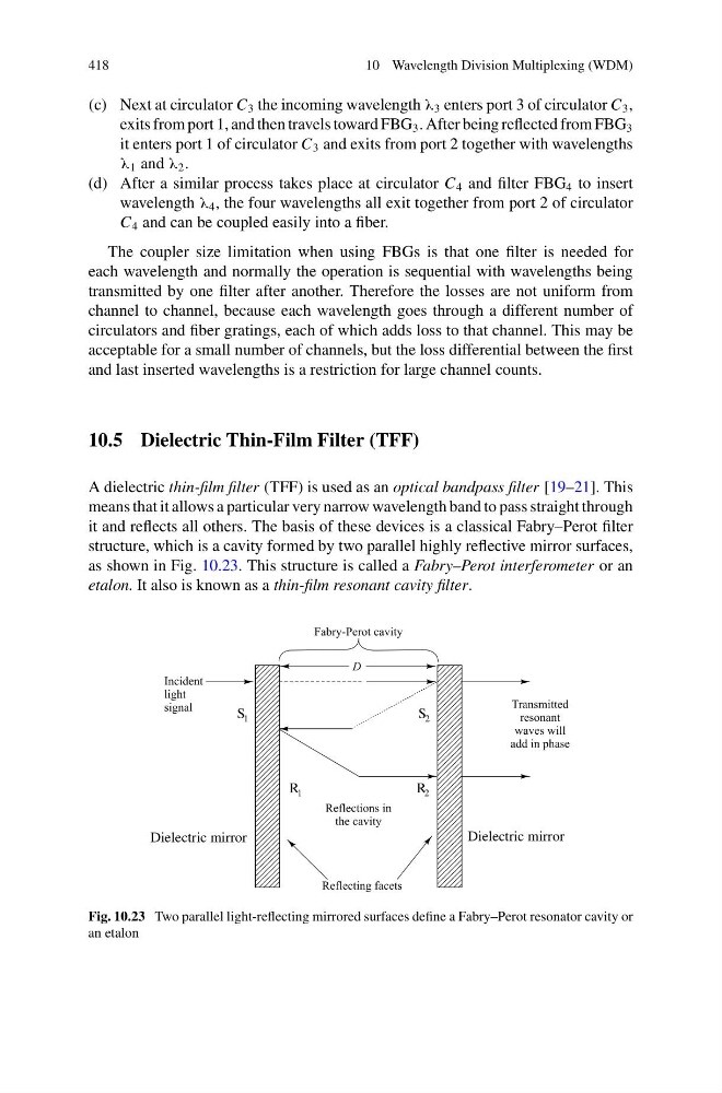
it and reflects all others. The basis of these devices is a classical Fabry–Perot filter
structure, which is a cavity formed by two parallel highly reflective mirror surfaces,
as shown in Fig. 10.23. This structure is called a Fabry–Perot interferometer or an
etalon. It also is known as a thin-film resonant cavity filter.
S 1
S 2
Dielectric mirror
Dielectric mirror
R 1
R 2
Fig. 10.23 Two parallel light-reflecting mirrored surfaces define a Fabry–Perot resonator cavity or
an etalon
10 Wavelength Division Multiplexing (WDM)
(c) Next at circulator C 3 the incoming wavelength λ 3 enters port 3 of circulator C 3 ,
exits from port 1, and then travels toward FBG 3 . After being reflected from FBG 3
it enters port 1 of circulator C 3 and exits from port 2 together with wavelengths
λ 1 and λ 2 .
(d) After a similar process takes place at circulator C 4 and filter FBG 4 to insert
wavelength λ 4 , the four wavelengths all exit together from port 2 of circulator
C 4 and can be coupled easily into a fiber.
The coupler size limitation when using FBGs is that one filter is needed for
each wavelength and normally the operation is sequential with wavelengths being
transmitted by one filter after another. Therefore the losses are not uniform from
channel to channel, because each wavelength goes through a different number of
circulators and fiber gratings, each of which adds loss to that channel. This may be
acceptable for a small number of channels, but the loss differential between the first
and last inserted wavelengths is a restriction for large channel counts.
10.5 Dielectric Thin-Film Filter (TFF)
A dielectric thin-film filter (TFF) is used as an optical bandpass filter [19–21]. This
means that it allows a particular very narrow wavelength band to pass straight through
it and reflects all others. The basis of these devices is a classical Fabry–Perot filter
structure, which is a cavity formed by two parallel highly reflective mirror surfaces,
as shown in Fig. 10.23. This structure is called a Fabry–Perot interferometer or an
etalon. It also is known as a thin-film resonant cavity filter.
S 1
S 2
Dielectric mirror
Dielectric mirror
R 1
R 2
Fig. 10.23 Two parallel light-reflecting mirrored surfaces define a Fabry–Perot resonator cavity or
an etalon