

416
10 Wavelength Division Multiplexing (WDM)
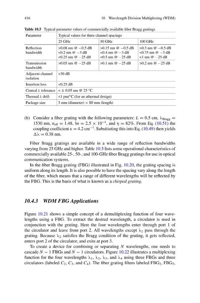
Table 10.5 Typical parameter values of commercially available fiber Bragg gratings
Parameter
Typical values for three channel spacings
25 GHz
50 GHz
100 GHz
Reflection
bandwidth
>0.08 nm @ −0.5 dB
<0.2 nm @ −3 dB
<0.25 nm @ −25 dB
>0.15 nm @ −0.5 dB
<0.4 nm @ −3 dB
<0.5 nm @ −25 dB
>0.3 nm @ −0.5 dB
<0.75 nm @ −3 dB
<1 nm @ −25 dB
Transmission
bandwidth
>0.05 nm @ −25 dB
>0.1 nm @ −25 dB
>0.2 nm @ −25 dB
Adjacent channel
isolation
>30 dB
Insertion loss
<0.25 dB
Central λ tolerance < ± 0.05 nm @ 25 °C
Thermal λ drift
<1 pm/°C (for an athermal design)
Package size
5 mm (diameter) × 80 mm (length)
(b) Consider a fiber grating with the following parameters: L = 0.5 cm, λ Bragg =
1530 nm, n eff = 1.48, δn = 2.5 × 10
−4 , and η = 82%. From Eq. (10.51) the
coupling coefficient κ = 4.2 cm
−1 . Substituting this into Eq. (10.49) then yields
λ = 0.38 nm.
Fiber Bragg gratings are available in a wide range of reflection bandwidths
varying from 25 GHz and higher. Table 10.5 lists some operational characteristics of
commercially available 25-, 50-, and 100-GHz fiber Bragg gratings for use in optical
communication systems.
In the fiber Bragg grating (FBG) illustrated in Fig. 10.20, the grating spacing is
uniform along its length. It is also possible to have the spacing vary along the length
of the fiber, which means that a range of different wavelengths will be reflected by
the FBG. This is the basis of what is known as a chirped grating.
10.4.3 WDM FBG Applications
Figure 10.21 shows a simple concept of a demultiplexing function of four wavelengths using a FBG. To extract the desired wavelength, a circulator is used in
conjunction with the grating. Here the four wavelengths enter through port 1 of
the circulator and leave from port 2. All wavelengths except λ 2 pass through the
grating. Because λ 2 satisfies the Bragg condition of the grating, it gets reflected,
enters port 2 of the circulator, and exits at port 3.
To create a device for combining or separating N wavelengths, one needs to
cascade N − 1 FBGs and N − 1 circulators. Figure 10.22 illustrates a multiplexing
function for the four wavelengths λ 1 , λ 2 , λ 3 , and λ 4 using three FBGs and three
circulators (labeled C 2 , C 3 , and C 4 ). The fiber grating filters labeled FBG 2 , FBG 3 ,
10 Wavelength Division Multiplexing (WDM)
Table 10.5 Typical parameter values of commercially available fiber Bragg gratings
Parameter
Typical values for three channel spacings
25 GHz
50 GHz
100 GHz
Reflection
bandwidth
>0.08 nm @ −0.5 dB
<0.2 nm @ −3 dB
<0.25 nm @ −25 dB
>0.15 nm @ −0.5 dB
<0.4 nm @ −3 dB
<0.5 nm @ −25 dB
>0.3 nm @ −0.5 dB
<0.75 nm @ −3 dB
<1 nm @ −25 dB
Transmission
bandwidth
>0.05 nm @ −25 dB
>0.1 nm @ −25 dB
>0.2 nm @ −25 dB
Adjacent channel
isolation
>30 dB
Insertion loss
<0.25 dB
Central λ tolerance < ± 0.05 nm @ 25 °C
Thermal λ drift
<1 pm/°C (for an athermal design)
Package size
5 mm (diameter) × 80 mm (length)
(b) Consider a fiber grating with the following parameters: L = 0.5 cm, λ Bragg =
1530 nm, n eff = 1.48, δn = 2.5 × 10
−4 , and η = 82%. From Eq. (10.51) the
coupling coefficient κ = 4.2 cm
−1 . Substituting this into Eq. (10.49) then yields
λ = 0.38 nm.
Fiber Bragg gratings are available in a wide range of reflection bandwidths
varying from 25 GHz and higher. Table 10.5 lists some operational characteristics of
commercially available 25-, 50-, and 100-GHz fiber Bragg gratings for use in optical
communication systems.
In the fiber Bragg grating (FBG) illustrated in Fig. 10.20, the grating spacing is
uniform along its length. It is also possible to have the spacing vary along the length
of the fiber, which means that a range of different wavelengths will be reflected by
the FBG. This is the basis of what is known as a chirped grating.
10.4.3 WDM FBG Applications
Figure 10.21 shows a simple concept of a demultiplexing function of four wavelengths using a FBG. To extract the desired wavelength, a circulator is used in
conjunction with the grating. Here the four wavelengths enter through port 1 of
the circulator and leave from port 2. All wavelengths except λ 2 pass through the
grating. Because λ 2 satisfies the Bragg condition of the grating, it gets reflected,
enters port 2 of the circulator, and exits at port 3.
To create a device for combining or separating N wavelengths, one needs to
cascade N − 1 FBGs and N − 1 circulators. Figure 10.22 illustrates a multiplexing
function for the four wavelengths λ 1 , λ 2 , λ 3 , and λ 4 using three FBGs and three
circulators (labeled C 2 , C 3 , and C 4 ). The fiber grating filters labeled FBG 2 , FBG 3 ,