

336
8 Digital Optical Fiber Links
The cyclic redundancy check technique is based on a binary division process
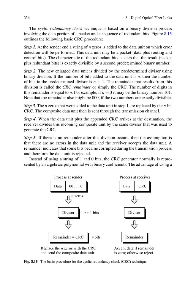
involving the data portion of a packet and a sequence of redundant bits. Figure 8.15
outlines the following basic CRC procedure:
Step 1. At the sender end a string of n zeros is added to the data unit on which error
detection will be performed. This data unit may be a packet (data plus routing and
control bits). The characteristic of the redundant bits is such that the result (packet
plus redundant bits) is exactly divisible by a second predetermined binary number.
Step 2. The new enlarged data unit is divided by the predetermined divisor using
binary division. If the number of bits added to the data unit is n, then the number
of bits in the predetermined divisor is n + 1. The remainder that results from this
division is called the CRC remainder or simply the CRC. The number of digits in
this remainder is equal to n. For example, if n = 3 it may be the binary number 101.
Note that the remainder also might be 000, if the two numbers are exactly divisible.
Step 3. The n zeros that were added to the data unit in step 1 are replaced by the n-bit
CRC. The composite data unit then is sent through the transmission channel.
Step 4. When the data unit plus the appended CRC arrives at the destination, the
receiver divides this incoming composite unit by the same divisor that was used to
generate the CRC.
Step 5. If there is no remainder after this division occurs, then the assumption is
that there are no errors in the data unit and the receiver accepts the data unit. A
remainder indicates that some bits became corrupted during the transmission process
and therefore the data unit is rejected.
Instead of using a string of 1 and 0 bits, the CRC generator normally is represented by an algebraic polynomial with binary coefficients. The advantage of using a
Fig. 8.15 The basic procedure for the cyclic redundancy check (CRC) technique
8 Digital Optical Fiber Links
The cyclic redundancy check technique is based on a binary division process
involving the data portion of a packet and a sequence of redundant bits. Figure 8.15
outlines the following basic CRC procedure:
Step 1. At the sender end a string of n zeros is added to the data unit on which error
detection will be performed. This data unit may be a packet (data plus routing and
control bits). The characteristic of the redundant bits is such that the result (packet
plus redundant bits) is exactly divisible by a second predetermined binary number.
Step 2. The new enlarged data unit is divided by the predetermined divisor using
binary division. If the number of bits added to the data unit is n, then the number
of bits in the predetermined divisor is n + 1. The remainder that results from this
division is called the CRC remainder or simply the CRC. The number of digits in
this remainder is equal to n. For example, if n = 3 it may be the binary number 101.
Note that the remainder also might be 000, if the two numbers are exactly divisible.
Step 3. The n zeros that were added to the data unit in step 1 are replaced by the n-bit
CRC. The composite data unit then is sent through the transmission channel.
Step 4. When the data unit plus the appended CRC arrives at the destination, the
receiver divides this incoming composite unit by the same divisor that was used to
generate the CRC.
Step 5. If there is no remainder after this division occurs, then the assumption is
that there are no errors in the data unit and the receiver accepts the data unit. A
remainder indicates that some bits became corrupted during the transmission process
and therefore the data unit is rejected.
Instead of using a string of 1 and 0 bits, the CRC generator normally is represented by an algebraic polynomial with binary coefficients. The advantage of using a
Fig. 8.15 The basic procedure for the cyclic redundancy check (CRC) technique