

8.2 Concepts of Link Power Penalties
327
In practice, optical transmitters have minimum extinction ratios ranging from 7
to 10 (8.5–10 dB), for which the power penalties range from 1.25 to 0.87 dB. A
minimum extinction ratio of 18 is needed in order to have a power penalty of less
than 0.5 dB. Note that the power penalty increases significantly for lower extinction
ratios.
Drill Problem 8.5 (a) Show that for an extinction ratio r e = 8 the power
penalty is 1.09 dB. (b) Show that a minimum extinction ratio of 18 is needed
to have a power penalty of less than 0.5 dB.
8.2.4 Modal Noise Power Penalties
When light from a coherent laser is launched into a multimode fiber, normally a
number of propagating modes of the fiber are excited [23, 24]. As long as these
modes retain their relative phase coherence, the radiation pattern seen at the end of
the fiber (or at any point along the fiber) takes on the form of a speckle pattern.
This is the result of constructive and destructive interference between propagating
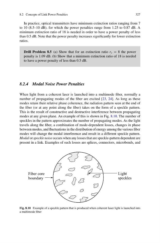
modes at any given plane. An example of this is shown in Fig. 8.10. The number of
speckles in the pattern approximates the number of propagating modes. As the light
travels along the fiber, a combination of mode-dependent losses, changes in phase
between modes, and fluctuations in the distribution of energy among the various fiber
modes will change the modal interference and result in a different speckle pattern.
Modal or speckle noise occurs when any losses that are speckle-pattern dependent are
present in a link. Examples of such losses are splices, connectors, microbends, and
Fig. 8.10 Example of a speckle pattern that is produced when coherent laser light is launched into
a multimode fiber
327
In practice, optical transmitters have minimum extinction ratios ranging from 7
to 10 (8.5–10 dB), for which the power penalties range from 1.25 to 0.87 dB. A
minimum extinction ratio of 18 is needed in order to have a power penalty of less
than 0.5 dB. Note that the power penalty increases significantly for lower extinction
ratios.
Drill Problem 8.5 (a) Show that for an extinction ratio r e = 8 the power
penalty is 1.09 dB. (b) Show that a minimum extinction ratio of 18 is needed
to have a power penalty of less than 0.5 dB.
8.2.4 Modal Noise Power Penalties
When light from a coherent laser is launched into a multimode fiber, normally a
number of propagating modes of the fiber are excited [23, 24]. As long as these
modes retain their relative phase coherence, the radiation pattern seen at the end of
the fiber (or at any point along the fiber) takes on the form of a speckle pattern.
This is the result of constructive and destructive interference between propagating
modes at any given plane. An example of this is shown in Fig. 8.10. The number of
speckles in the pattern approximates the number of propagating modes. As the light
travels along the fiber, a combination of mode-dependent losses, changes in phase
between modes, and fluctuations in the distribution of energy among the various fiber
modes will change the modal interference and result in a different speckle pattern.
Modal or speckle noise occurs when any losses that are speckle-pattern dependent are
present in a link. Examples of such losses are splices, connectors, microbends, and
Fig. 8.10 Example of a speckle pattern that is produced when coherent laser light is launched into
a multimode fiber