

8.1 Basic Optical Fiber Links
319
8.1.5 Transmission at Short Wavelengths
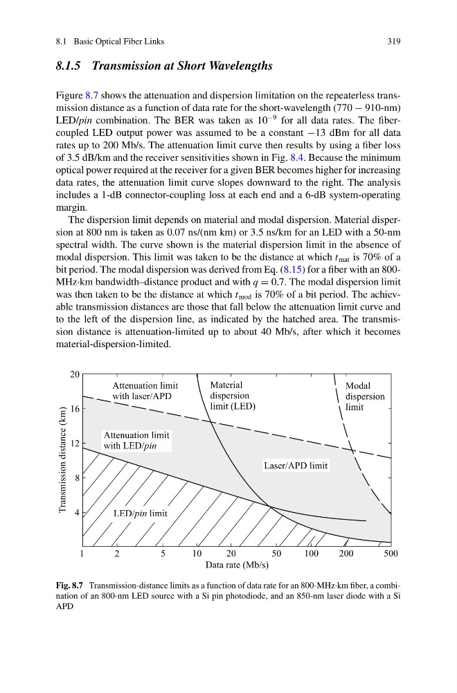
Figure 8.7 shows the attenuation and dispersion limitation on the repeaterless transmission distance as a function of data rate for the short-wavelength (770 − 910-nm)
LED/pin combination. The BER was taken as 10
−9 for all data rates. The fibercoupled LED output power was assumed to be a constant −13 dBm for all data
rates up to 200 Mb/s. The attenuation limit curve then results by using a fiber loss
of 3.5 dB/km and the receiver sensitivities shown in Fig. 8.4. Because the minimum
optical power required at the receiver for a given BER becomes higher for increasing
data rates, the attenuation limit curve slopes downward to the right. The analysis
includes a 1-dB connector-coupling loss at each end and a 6-dB system-operating
margin.
The dispersion limit depends on material and modal dispersion. Material dispersion at 800 nm is taken as 0.07 ns/(nm km) or 3.5 ns/km for an LED with a 50-nm
spectral width. The curve shown is the material dispersion limit in the absence of
modal dispersion. This limit was taken to be the distance at which t mat is 70% of a
bit period. The modal dispersion was derived from Eq. (8.15) for a fiber with an 800MHz·km bandwidth–distance product and with q = 0.7. The modal dispersion limit
was then taken to be the distance at which t mod is 70% of a bit period. The achievable transmission distances are those that fall below the attenuation limit curve and
to the left of the dispersion line, as indicated by the hatched area. The transmission distance is attenuation-limited up to about 40 Mb/s, after which it becomes
material-dispersion-limited.
Fig. 8.7 Transmission-distance limits as a function of data rate for an 800-MHz·km fiber, a combination of an 800-nm LED source with a Si pin photodiode, and an 850-nm laser diode with a Si
APD
319
8.1.5 Transmission at Short Wavelengths
Figure 8.7 shows the attenuation and dispersion limitation on the repeaterless transmission distance as a function of data rate for the short-wavelength (770 − 910-nm)
LED/pin combination. The BER was taken as 10
−9 for all data rates. The fibercoupled LED output power was assumed to be a constant −13 dBm for all data
rates up to 200 Mb/s. The attenuation limit curve then results by using a fiber loss
of 3.5 dB/km and the receiver sensitivities shown in Fig. 8.4. Because the minimum
optical power required at the receiver for a given BER becomes higher for increasing
data rates, the attenuation limit curve slopes downward to the right. The analysis
includes a 1-dB connector-coupling loss at each end and a 6-dB system-operating
margin.
The dispersion limit depends on material and modal dispersion. Material dispersion at 800 nm is taken as 0.07 ns/(nm km) or 3.5 ns/km for an LED with a 50-nm
spectral width. The curve shown is the material dispersion limit in the absence of
modal dispersion. This limit was taken to be the distance at which t mat is 70% of a
bit period. The modal dispersion was derived from Eq. (8.15) for a fiber with an 800MHz·km bandwidth–distance product and with q = 0.7. The modal dispersion limit
was then taken to be the distance at which t mod is 70% of a bit period. The achievable transmission distances are those that fall below the attenuation limit curve and
to the left of the dispersion line, as indicated by the hatched area. The transmission distance is attenuation-limited up to about 40 Mb/s, after which it becomes
material-dispersion-limited.
Fig. 8.7 Transmission-distance limits as a function of data rate for an 800-MHz·km fiber, a combination of an 800-nm LED source with a Si pin photodiode, and an 850-nm laser diode with a Si
APD