

8.1 Basic Optical Fiber Links
317
Using Eq. (8.6) for the 3-dB optical bandwidth of the fiber link and letting t FWHM
be the rise time resulting from modal dispersion, then, from Eq. (8.14),
t mod =
0.44
B M
=
0.44L
q
B 0
(8.15)
If t mod is expressed in nanoseconds and B M is given in megahertz, then
t mod =
440
B M
=
440L
q
B 0
(8.16)
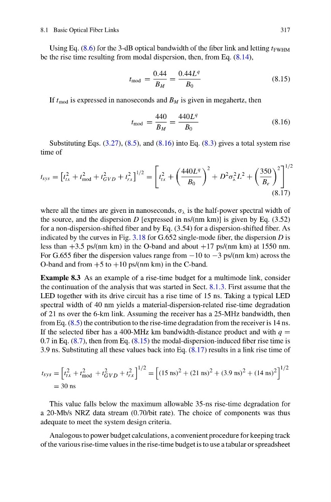
Substituting Eqs. (3.27), (8.5), and (8.16) into Eq. (8.3) gives a total system rise
time of
t sys =
t
2
t x + t
2
mod + t
2
GV D + t
2
r x
1/2 =
t
2
t x +
440L
q
B 0
2
+ D
2
σ
2
λ L
2
+
350
B e
2
1/2
(8.17)
where all the times are given in nanoseconds, σ λ is the half-power spectral width of
the source, and the dispersion D [expressed in ns/(nm km)] is given by Eq. (3.52)
for a non-dispersion-shifted fiber and by Eq. (3.54) for a dispersion-shifted fiber. As
indicated by the curves in Fig. 3.18 for G.652 single-mode fiber, the dispersion D is
less than +3.5 ps/(nm km) in the O-band and about +17 ps/(nm km) at 1550 nm.
For G.655 fiber the dispersion values range from −10 to −3 ps/(nm km) across the
O-band and from +5 to +10 ps/(nm km) in the C-band.
Example 8.3 As an example of a rise-time budget for a multimode link, consider
the continuation of the analysis that was started in Sect. 8.1.3. First assume that the
LED together with its drive circuit has a rise time of 15 ns. Taking a typical LED
spectral width of 40 nm yields a material-dispersion-related rise-time degradation
of 21 ns over the 6-km link. Assuming the receiver has a 25-MHz bandwidth, then
from Eq. (8.5) the contribution to the rise-time degradation from the receiver is 14 ns.
If the selected fiber has a 400-MHz km bandwidth-distance product and with q =
0.7 in Eq. (8.7), then from Eq. (8.15) the modal-dispersion-induced fiber rise time is
3.9 ns. Substituting all these values back into Eq. (8.17) results in a link rise time of
t sys =
t 2
t x + t 2
mod + t 2
GV D + t 2
r x
1/2 =
(15 ns) 2 + (21 ns) 2 + (3.9 ns) 2 + (14 ns) 2
1/2
= 30 ns
This value falls below the maximum allowable 35-ns rise-time degradation for
a 20-Mb/s NRZ data stream (0.70/bit rate). The choice of components was thus
adequate to meet the system design criteria.
Analogous to power budget calculations, a convenient procedure for keeping track
of the various rise-time values in the rise-time budget is to use a tabular or spreadsheet
317
Using Eq. (8.6) for the 3-dB optical bandwidth of the fiber link and letting t FWHM
be the rise time resulting from modal dispersion, then, from Eq. (8.14),
t mod =
0.44
B M
=
0.44L
q
B 0
(8.15)
If t mod is expressed in nanoseconds and B M is given in megahertz, then
t mod =
440
B M
=
440L
q
B 0
(8.16)
Substituting Eqs. (3.27), (8.5), and (8.16) into Eq. (8.3) gives a total system rise
time of
t sys =
t
2
t x + t
2
mod + t
2
GV D + t
2
r x
1/2 =
t
2
t x +
440L
q
B 0
2
+ D
2
σ
2
λ L
2
+
350
B e
2
1/2
(8.17)
where all the times are given in nanoseconds, σ λ is the half-power spectral width of
the source, and the dispersion D [expressed in ns/(nm km)] is given by Eq. (3.52)
for a non-dispersion-shifted fiber and by Eq. (3.54) for a dispersion-shifted fiber. As
indicated by the curves in Fig. 3.18 for G.652 single-mode fiber, the dispersion D is
less than +3.5 ps/(nm km) in the O-band and about +17 ps/(nm km) at 1550 nm.
For G.655 fiber the dispersion values range from −10 to −3 ps/(nm km) across the
O-band and from +5 to +10 ps/(nm km) in the C-band.
Example 8.3 As an example of a rise-time budget for a multimode link, consider
the continuation of the analysis that was started in Sect. 8.1.3. First assume that the
LED together with its drive circuit has a rise time of 15 ns. Taking a typical LED
spectral width of 40 nm yields a material-dispersion-related rise-time degradation
of 21 ns over the 6-km link. Assuming the receiver has a 25-MHz bandwidth, then
from Eq. (8.5) the contribution to the rise-time degradation from the receiver is 14 ns.
If the selected fiber has a 400-MHz km bandwidth-distance product and with q =
0.7 in Eq. (8.7), then from Eq. (8.15) the modal-dispersion-induced fiber rise time is
3.9 ns. Substituting all these values back into Eq. (8.17) results in a link rise time of
t sys =
t 2
t x + t 2
mod + t 2
GV D + t 2
r x
1/2 =
(15 ns) 2 + (21 ns) 2 + (3.9 ns) 2 + (14 ns) 2
1/2
= 30 ns
This value falls below the maximum allowable 35-ns rise-time degradation for
a 20-Mb/s NRZ data stream (0.70/bit rate). The choice of components was thus
adequate to meet the system design criteria.
Analogous to power budget calculations, a convenient procedure for keeping track
of the various rise-time values in the rise-time budget is to use a tabular or spreadsheet