

304
8 Digital Optical Fiber Links
detection process. In reality, various signal impairments can degrade the link performance. These impairments can reduce the power of the optical signal arriving
at the receiver from the ideal case, which is known as a power penalty for that
effect. Section 8.2 describes the power penalties associated with some key signal
impairments that may be observed in an optical link.
To control errors and to improve the reliability of a communication line, it is
necessary to be able to detect the errors and then correct them or retransmit the
information. Section 8.3 describes error detection and correction methods that are
used in a variety of optical fiber communication links. Basic coherent detection
schemes are addressed in Sect. 8.4. These schemes are used in place of directdetection methods to improve receiver sensitivities, especially for high-speed links
operating at 40 and 100 Gb/s. Chapter 13 describes additional signal modulation and
detection formats, such as differential phase-shift keying (DPSK) and differential
quadrature phase-shift keying (DQPSK).
Versatile and powerful modeling and simulation tools are commercially available
for doing many of the tasks described in this chapter. These software-based tools
can run on conventional personal computers and include functions such as estimations of the BER and power-penalty effects with different optical receiver models,
calculations of link power budgets, and simulation of link performance when using
different components.
8.1 Basic Optical Fiber Links
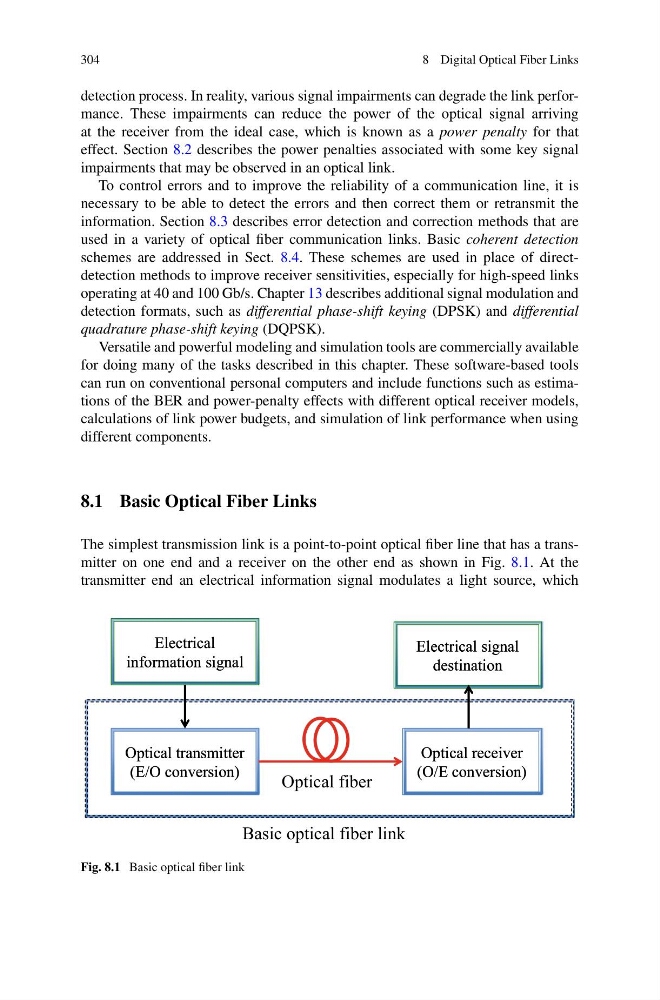
The simplest transmission link is a point-to-point optical fiber line that has a transmitter on one end and a receiver on the other end as shown in Fig. 8.1. At the
transmitter end an electrical information signal modulates a light source, which
Optical transmitter
(E/O conversion)
Optical transmitter
(E/O conversion)
Optical receiver
(O/E conversion)
Optical receiver
(O/E conversion)
Optical fiber
Electrical
information signal
Electrical
information signal
Electrical signal
destination
Electrical signal
destination
Basic optical fiber link
Fig. 8.1 Basic optical fiber link
8 Digital Optical Fiber Links
detection process. In reality, various signal impairments can degrade the link performance. These impairments can reduce the power of the optical signal arriving
at the receiver from the ideal case, which is known as a power penalty for that
effect. Section 8.2 describes the power penalties associated with some key signal
impairments that may be observed in an optical link.
To control errors and to improve the reliability of a communication line, it is
necessary to be able to detect the errors and then correct them or retransmit the
information. Section 8.3 describes error detection and correction methods that are
used in a variety of optical fiber communication links. Basic coherent detection
schemes are addressed in Sect. 8.4. These schemes are used in place of directdetection methods to improve receiver sensitivities, especially for high-speed links
operating at 40 and 100 Gb/s. Chapter 13 describes additional signal modulation and
detection formats, such as differential phase-shift keying (DPSK) and differential
quadrature phase-shift keying (DQPSK).
Versatile and powerful modeling and simulation tools are commercially available
for doing many of the tasks described in this chapter. These software-based tools
can run on conventional personal computers and include functions such as estimations of the BER and power-penalty effects with different optical receiver models,
calculations of link power budgets, and simulation of link performance when using
different components.
8.1 Basic Optical Fiber Links
The simplest transmission link is a point-to-point optical fiber line that has a transmitter on one end and a receiver on the other end as shown in Fig. 8.1. At the
transmitter end an electrical information signal modulates a light source, which
Optical transmitter
(E/O conversion)
Optical transmitter
(E/O conversion)
Optical receiver
(O/E conversion)
Optical receiver
(O/E conversion)
Optical fiber
Electrical
information signal
Electrical
information signal
Electrical signal
destination
Electrical signal
destination
Basic optical fiber link
Fig. 8.1 Basic optical fiber link