

288
7 Optical Receiver Operation
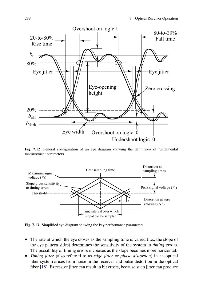
Fig. 7.12 General configuration of an eye diagram showing the definitions of fundamental
measurement parameters
Fig. 7.13 Simplified eye diagram showing the key performance parameters
• The rate at which the eye closes as the sampling time is varied (i.e., the slope of
the eye pattern sides) determines the sensitivity of the system to timing errors.
The possibility of timing errors increases as the slope becomes more horizontal.
• Timing jitter (also referred to as edge jitter or phase distortion) in an optical
fiber system arises from noise in the receiver and pulse distortion in the optical
fiber [18]. Excessive jitter can result in bit errors, because such jitter can produce
7 Optical Receiver Operation
Fig. 7.12 General configuration of an eye diagram showing the definitions of fundamental
measurement parameters
Fig. 7.13 Simplified eye diagram showing the key performance parameters
• The rate at which the eye closes as the sampling time is varied (i.e., the slope of
the eye pattern sides) determines the sensitivity of the system to timing errors.
The possibility of timing errors increases as the slope becomes more horizontal.
• Timing jitter (also referred to as edge jitter or phase distortion) in an optical
fiber system arises from noise in the receiver and pulse distortion in the optical
fiber [18]. Excessive jitter can result in bit errors, because such jitter can produce