

232
5 Optical Power Coupling
p =
cos θ A (1 − cos θ)
sin θ A sin θ
q =
cos
3
θ A
cos 2 θ A − sin
2
θ
3/2
y =
cos
2
θ A (1 − cos θ) − sin
2
θ
sin θ A cos θ A sinθ
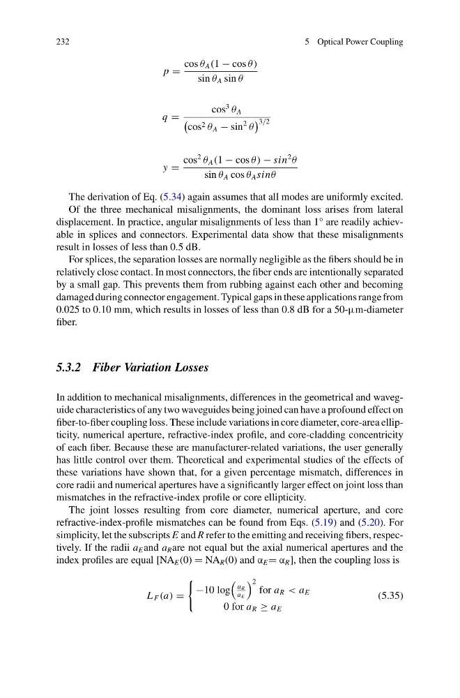
The derivation of Eq. (5.34) again assumes that all modes are uniformly excited.
Of the three mechanical misalignments, the dominant loss arises from lateral
displacement. In practice, angular misalignments of less than 1° are readily achievable in splices and connectors. Experimental data show that these misalignments
result in losses of less than 0.5 dB.
For splices, the separation losses are normally negligible as the fibers should be in
relatively close contact. In most connectors, the fiber ends are intentionally separated
by a small gap. This prevents them from rubbing against each other and becoming
damaged during connector engagement. Typical gaps in these applications range from
0.025 to 0.10 mm, which results in losses of less than 0.8 dB for a 50-μm-diameter
fiber.
5.3.2 Fiber Variation Losses
In addition to mechanical misalignments, differences in the geometrical and waveguide characteristics of any two waveguides being joined can have a profound effect on
fiber-to-fiber coupling loss. These include variations in core diameter, core-area ellipticity, numerical aperture, refractive-index profile, and core-cladding concentricity
of each fiber. Because these are manufacturer-related variations, the user generally
has little control over them. Theoretical and experimental studies of the effects of
these variations have shown that, for a given percentage mismatch, differences in
core radii and numerical apertures have a significantly larger effect on joint loss than
mismatches in the refractive-index profile or core ellipticity.
The joint losses resulting from core diameter, numerical aperture, and core
refractive-index-profile mismatches can be found from Eqs. (5.19) and (5.20). For
simplicity, let the subscripts E and R refer to the emitting and receiving fibers, respectively. If the radii a E and a R are not equal but the axial numerical apertures and the
index profiles are equal [NA E (0) = NA R (0) and α E = α R ], then the coupling loss is
L F (a) =
−10 log
a R
a E
2
for a R < a E
0 for a R ≥ a E
(5.35)
5 Optical Power Coupling
p =
cos θ A (1 − cos θ)
sin θ A sin θ
q =
cos
3
θ A
cos 2 θ A − sin
2
θ
3/2
y =
cos
2
θ A (1 − cos θ) − sin
2
θ
sin θ A cos θ A sinθ
The derivation of Eq. (5.34) again assumes that all modes are uniformly excited.
Of the three mechanical misalignments, the dominant loss arises from lateral
displacement. In practice, angular misalignments of less than 1° are readily achievable in splices and connectors. Experimental data show that these misalignments
result in losses of less than 0.5 dB.
For splices, the separation losses are normally negligible as the fibers should be in
relatively close contact. In most connectors, the fiber ends are intentionally separated
by a small gap. This prevents them from rubbing against each other and becoming
damaged during connector engagement. Typical gaps in these applications range from
0.025 to 0.10 mm, which results in losses of less than 0.8 dB for a 50-μm-diameter
fiber.
5.3.2 Fiber Variation Losses
In addition to mechanical misalignments, differences in the geometrical and waveguide characteristics of any two waveguides being joined can have a profound effect on
fiber-to-fiber coupling loss. These include variations in core diameter, core-area ellipticity, numerical aperture, refractive-index profile, and core-cladding concentricity
of each fiber. Because these are manufacturer-related variations, the user generally
has little control over them. Theoretical and experimental studies of the effects of
these variations have shown that, for a given percentage mismatch, differences in
core radii and numerical apertures have a significantly larger effect on joint loss than
mismatches in the refractive-index profile or core ellipticity.
The joint losses resulting from core diameter, numerical aperture, and core
refractive-index-profile mismatches can be found from Eqs. (5.19) and (5.20). For
simplicity, let the subscripts E and R refer to the emitting and receiving fibers, respectively. If the radii a E and a R are not equal but the axial numerical apertures and the
index profiles are equal [NA E (0) = NA R (0) and α E = α R ], then the coupling loss is
L F (a) =
−10 log
a R
a E
2
for a R < a E
0 for a R ≥ a E
(5.35)